granco: 720 Student Report
granco: 720 Student Report

Fellow Radiophiles:
Ron Roscoe taught the 6.102 RF laboratory course at MIT which included the analysis and restoration of antique AM-FM tube radio. Ron has recently retired, so the course is no longer available. The analysis and restoration processes served to put into practice the theoretical RF concepts that were taught in the course. I used to spend time with the students helping them and analysing together the many clever, and sometimes not so clever, circuits in these radios.
Nabila Agila is one of Ron's recent Electrical Engineering 6.102 students and she has kindly agreed to share her analysis and restoration report of her Granco 720 AM-FM radio in this forum.
Thank you Nabila, for sharing the following report. It was great fun watching your shrewd analysis and successful restoration work.
-Joe
Restoration of Antique Granco 720 Radio (1955)

This post documents the restoration of an antique AM/FM Granco 720 radio. It examines the design of the AM and the FM receiver. It details the alignment of the receivers, discusses repairs and evaluates the performance of the radio.

We restored the Granco 720 to full function.

1. OVERVIEW
Restoration of antique radios has a niche in the electrical engineering community. Engineering students, such as the author, become interested in the topic to learn about the history of their chosen profession and to learn RF concepts also found in modern circuits. It is an opportunity to learn from the masters and to study the innovation of our historic predecessors.
The purpose of this paper is to detail the restoration of a Granco 720 antique radio. It describes the radio, starting from the vacuum tubes up to the circuitry of the AM and the FM receiver. It describes the steps taken to make the radio electrically safer, repair detected problems, and alignment of the receiver. Also, we describe measurements taken to evaluate leakage of capacitors, expected DC bias voltages and the audio frequency response. Finally, we present a list errors and accidents that happened during restoration and how we fixed them.
We restored the Granco 720 radio to full function.
1.1 SPECIFICATIONS
The Granco 720 radio is a compact 7.5 x 5.1 x 5.5 inch molded plastic table top AM/FM set. It is an AC/DC super heterodyne set that works with 117V. It has 7 tubes, a slug tuner for FM and a tuning capacitor for AM. The audio output uses permanent magnet 4×6 inch loudspeaker with a moving coil [1].
1.2 HISTORICAL CONTEXT
The Granco 720 model was manufactured by Granco Products, Inc circa 1955. This company was founded after World War II by Seymour Nepolin [2]. Granco Products, Inc was located 36-17 20th Avenue, Long Island City, New York. The company’s research included FM, UHF, receivers and tuners, stereophonics, multiplexing, high fidelity, MF car receivers and electronic air purifiers [3] [4].
The 720 model followed the models CTU, LCU, MTU and 610. The first three models were UHF converters. The 610 model was an FM-only radio, the first radio of the company. Granco manufactured most of its devices in plastic, and the 610 model greatly reassembles the 720 model. It uses a similar chassis, tube locations, and the same plastic covering. Granco contributed to bring affordable and small FM radios to the mass market.
In 1959, a fire hit the Granco facilities and the company disappeared after troubles with the insurance settlement. This fire was started when a high wattage soldering iron ignited a wood bench and the stockroom with plastic cabinets next door.
After the fire, in 1960, Emerson Radio agreed for option to buy shares in Granco to provide working capital. According to the Benjamin Abrahms, president of Emerson Radio, ” FM has become increasingly interesting to us… [noting] that the sales of FM sets has been on the rise and that Granco is a leading producer of such sets…” . Emerson Radio became the exclusive marketing agent for Granco. In 1963 Emerson Radio sold its Granco shares and started manufacturing its own FM radios. On April 23, 1963, Granco filed for bankruptcy claiming liabilities of $640,543 and assets of $362,982. Years later, the founder of Granco started the Melsey Corporation to develop VHF and UHF oscillators and a grid-dip meter [3].
The next sections detail the specifics of the Granco 720 circuitry.
2. CIRCUIT DETAIL
This section describes how the Granco 720 works. First, we describe the characteristics of the tubes found in the radio. Then, we overview the stages involved in the radio operation. Third, we look into the details of how each stage works.
2.1 TUBES
The Granco 720 radio uses seven vacuum tubes of five different types. In this section, we describe the specifics of what each tube is designed to do. Table 1 describes the main features of the tubes. Table 2 shows the wiring and grid names. This will be useful when we study the schematic as a whole and interpret the circuit.
Table 1. Description of the type and function of the models of tubes in the radio. Comments indicate characteristics of each particular tube.

Table 2. Biasing diagrams and pin connections for the tubes in the radio from the original tube schematics.

The next section presents the general structure of the radio circuitry.
2.2 OVERVIEW OF STAGES
The Granco 720 radio is a low cost AM/FM receiver. From a high level, the FM receiver uses a internal and AC wire antenna, an FM radio frequency amplifier, a FM mixer/oscillator, two FM intermediate frequencies (IF) amplifier stages, a ratio detector, an audio frequency (AF) amplifier, a power output tube and an output transformer. The AM receiver uses a loop antenna, an AM converter, one AM IF stage, a diode AM detector, an audio amplifier, power tube output and an output transformer. Figure 1 shows a summary of these stages, along with the shared AM/FM stages.

Figure 1. High level description of the circuitry of a Granco 720. Dashed boxes show dual use tubes for both AM and FM.
The next section will describe each stage in detail.
2.3 DETAILED ANALYSIS OF STAGES
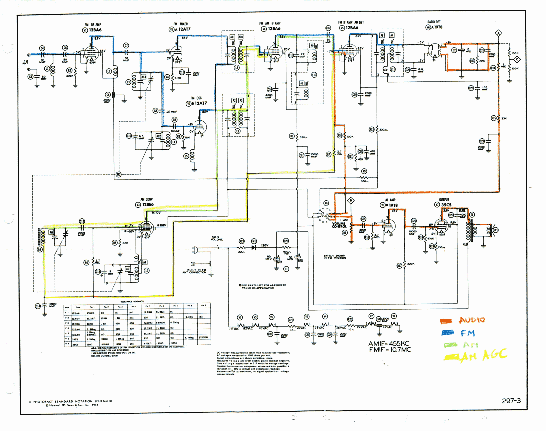
Here, we will describe the functioning of each detail. We combine what we know about the tubes used, the biasing scheme and how each element contributes to the function of the stage. Color coded schematics are attached at the end of this paper.
2.3.1 POWER SUPPLY
Before discussing the stages involved in the AM and FM receiver, we will discuss the power supply of the Granco 720. Here we will discuss the filament voltage and the B+ line.
The tubes’ filaments are connected in series to unregulated power coming from the AC cord. The sum of the filament voltage is 117 Volts and the tube specifications state that they draw 0.15A of current. Capacitors C31, C30 and C29 bypass any high frequencies on the filament line.
The B+ line that supplies the plate voltages is rectified with diode M1, which is a half-wave rectifier of the AC input. M1 cuts out the negative side of the AC. The positive AC goes through the filter C1A, C1B and R22.
Next, we discuss the stages of the AM and FM receiver.
2.3.2 FM RADIO FREQUENCY AMPLIFIER
This stage uses a 12BA6 V1 tube with a grounded cathode. The Granco 720 has an FM antenna built into the AC cord and internal connections that we used for a dipole antenna.
The screen grid decreases the Miller effect. The suppressor grid prevents the bouncing back of electrons. It uses 12.6V and a partially space charged grid with remote cutoff characteristic. The remote control cutoff characteristic implies that for a large bias, the tube transconductance decreases, limiting the gain, preventing overdrive and distortion but never fully cuts off the plate current. L1, C5 and R2 behave as a high pass filter.
2.3.3 FM MIXER AND OSCILLATOR
This stage uses a 12AT7 double triode V2A and V2B for mixing and oscillation. The tuning nub changes adjust the variable capacitor in A12 and A13. L3 has one more turn than L4 and therefore a higher inductance. The FM oscillator V2B tunes to the desired frequency and creates a large enough signal that drives the mixer into non-linearity and mixes with the signal. This mixing in a heterodyne occurs when the input signal multiplies with the oscillator frequency. The mixing result has several frequency components: the original signal, the oscillator signal, the absolute sum of frequencies, the absolute difference of the frequencies and higher order harmonics. For example, if the oscillator frequency is x, and the incoming signal has a frequency y, mixing will result in components x + y and abs (x – y). Also, oscillation requires meeting the Barkhausen conditions: a loop gain of 1 and a phase shift around the feedback loop equal to a multiple of 2 π.
The required oscillator frequency is achieved through a combination of A12, the intergrid capacitances and the cathode choke L5. The small C8 makes the contribution of A13 insignificant. C11 bypasses a self-biased triode V2A that is biased with R4.
2.3.4 FM INTERMEDIATE FREQUENCY AMPLIFIERS
There are two FM intermediate frequency amplifiers V4 and V5. Both use 12BA6 tubes. The signal coming from the mixer V2 enters the first FM IF coil A11 and A10. It enters a grounded cathode 12BA6, enters a FM transformer A9, passes through a DC coupling capacitor C17.
The intermediate frequency amplifiers control the selectivity and gain of the receiver by amplifying the carrier frequency, same as the intermediate frequency. This explains why the IF tuned circuits have fixed tuning and are adjusted to their optimum values turning receiver tuning but not by the user.
2.3.5 RATIO DETECTOR
This stage uses two diodes from the tube 19T8 in V6. It demodulates the amplified RF mixed signal and produces an audio output for further amplification. It is a detector demodulator. It responds to variations in frequency and not variations in amplitude of the signal without using additional limiter stages. It is much less sensitive to AM than to FM. Both diode currents flow through the resistor R13. The 240ms time constant of 22k and 2uF prevents response to undesired modulations of signal amplitude.
The primary and the secondary of the transformer A8 and A7 tune to the intermediate frequency. .L11 is tightly wound to the primary A7, which keeps a variable phase between the secondary and L11. When the incoming frequency matches the IF tuned of the transformer, the signal across A8 has a 0 degree phase difference with A7. When the signal moves away from IF, the phase difference between the primary and secondary changes, causing a variation of the phase between the secondary and L11. This produces a voltage distribution across the sides of the secondary and a current flow through L11 [5]. The detector diodes (pointing at opposite directions) will conduct depending on the sign of the difference between the received frequency and the IF. The loop of this diode current goes through the stabilizer capacitor C2 that will filter out the AM, along with the L11 will produce a demodulated output. There is no automatic volume control feedback loop for FM.
This stage has “soft limiting” built in the circuitry without diagonal distortion[6]. R10 in parallel with C17 are fast enough to follow spurious AM content and avoid diagonal distortion. Given that it is not a discriminator detector, there is not a dedicated limiting stage. The output of the FM IF amplifier V5 goes through the primary of the ratio detector A8, capacitor C19, and resistors R12 and R9 back to the FM mixer, and the input of the first FM IF amplifier. Diagonal distortion causes the a diagonal dip on the modulated signal until the capacitors get charged. Soft limiting occurs when the positive input envelope is pushed onto the negative envelope creating twice modulated negative envelope. Then, the negative side of the modulated envelope gets cutoff if it is beyond the grid cutoff point of the tube. Overall, this causes limiting of both the positive and the negative sides of the envelope [7].
2.3.6 AM CONVERTER
This stage uses a heptode pentagrid converter 12BE6 V3. The input signal comes from a loop-stick antenna tuned by the variable capacitors A6. Then it passes through a high pass filter that filters out frequencies below 30Hz. The signal mixes with the output of a Hartley oscillator with a tapped inductor and a gimmick that stands for a capacitor. The oscillating action occurs at section A5. On a Hartley oscillator, the amplitude is not changed over a frequency range but it will take noise from the amplifier or the LC circuit. The frequency of the Hartley oscillator is tuned by the tuning knob of the radio. The oscillator produces a large signal that in mixing with the AM signal will vary the current of cathode to plate current.
AM mixing follows the heterodyne sum and difference of frequency model, as described on the FM mixer and oscillator section.
2.3.7 AM INTERMEDIATE FREQUENCY AMPLIFIER
The AM intermediate frequency amplification occurs in stage V4. The output of the pentagrid converter enters the first AM intermediate frequency transformer A2 and A3. Then, it goes to the secondary of the first FM IF coil A10. At the AM frequencies, the coil A10 will have a very small impedance. The signal enters tube V4 where it is amplified to be later combined with the output of a second AM IF transformer A1.
2.3.8 AM DETECTOR
The output of the RF amplifier is demodulated in stage V5. RF goes through a coupling capacitor and is demodulated by the grid-to-cathode diode of the pentode. The DC voltage from this effect is taken through automatic gain control with a time constant of R7 and C14, where it will later change the grid to cathode voltage in the RF AM amplifier V4. Automatic gain control will change the DC Q point of this amplifier and reduce its gain if the DC is large. The DC voltage for automatic gain control has a negative polarity with respect to ground after the grid-to-cathode detector shorts the positive side of the signal and leaving a signal with a negative DC component.
The voltage across the AM detector diode goes through the audio stages through the time constant of R11 || R1 and C18. R10 prevents the loading of the stage by C18.
2.3.9 AUDIO FREQUENCY AMPLIFIER
The audio frequency stage is common to the audio output of AM and FM. The audio signal goes through a potentiometer R1 that controls the volume, a DC coupling capacitor C24. Amplification occurs at the triode section of tube V6B. Tube V6B is a 19T8 with a grounded cathode that is biased with resistor R16. R16 facilitates the accumulation of space charge on the grid with a large resistor value that prevents them from reaching ground. The space charge characteristic also manifests on a relatively lower plate voltage of 45V, half to a third of other plate voltages in the circuit. All other plates have a low DC resistance to the supply. V6 has a 220k resistance to the supply.
2.3.10 OUTPUT
The radio output uses a power 35C5 tube V3 that connects to an output transformer and then to a 3 ohm impedance speaker. Tube V3 is a self bias with a small resistor R19 connected to the cathode and a large resistor R18 to the grid. The combination of C25 and R18 also filters out non audible low frequencies. The power tube produces a larger plate current to drive the output transformer T1, which in turn drives speaker SP1.
2.4 OTHER ELEMENTS OF THE RADIO
Two elements of the radio stand out for their mechanical design: a rotary switch and the FM tuning mechanism.
2.4.1 ROTARY AM/FM SWITCH
This mechanical switch selects the AM or FM band. It controls the distribution of B+ between AM/FM and the input to the audio amplification coming from the AM or FM detector. It is a two sided switch that shorts two leads at the time, and non-intuitive to read. The left section shorts the B+ coming from the filtered rectified AC power and provides power to either the FM or the AM tubes. The right section selects the audio from AM or FM and takes it to the common audio amplification section.

Figure 2. Rotary switch for AM/FM bands. The left switch provides power to the relevant tubes. The right section selects which audio output to amplify at the later audio amplifier stages.
2.4.2 FM TUNING MECHANISM
Granco Inc had the patents for its FM tuning mechanism. This is probably the reason behind the Emerson Radio investment mentioned in the Historical Context section of this paper. Two patents by : “High frequency tuners” [8] and “Tuner chassis with integral shield and condenser plate” [9] are relevant to this radio. The first describes two variable capacitors that are adjusted by with a common bracket that pushes plungers inside of the capacitors. The bracket is adjusted with a shaft screw mechanism. The second patent describes that same mechanism and refines the design to add a shield chassis. Figure 3 shows a picture of the FM tuning mechanism in my radio next to a figure from the original patent.

Figure 3. FM Tuning mechanism. A common bracket adjusts plungers varying capacitance. Left shows a picture from the restored radio. Right shows figure from original patent.
The Granco 720 radio has a plastic cover. Therefore, the role of the chassis box described in the patent is fulfilled by the metal plate between the plungers and the metal walls on top and below the mechanism. The middle metal plate is perpendicular to the wall and is parallel to the coils. It provides shielding between the left and right sections of the mechanism. The shaft allows for tightly controlled tuning and makes the tuning resistant to external bumps.
The next section details the repairs to bring the radio back to full function.
3. REPAIR DESCRIPTION
The difficulty in repair of this radio is its compact size. All the electronics are tightly soldered together with little leeway to use a soldering iron or to probe the components with an oscilloscope or a digital meter. This section describes the repairs to make the radio electrically safer and to improve its performance and physical appearance.
3.1 SAFETY CHANGES
The Granco 720 model is a hot chassis AC-DC radio. Although the schematic indicates that the on/off switch is located at the hot line following modern safety standards, visual examination revealed that the on/off switch was in fact located at the neutral wire. We rewired the switch to the voltage line instead of the neutral.
The original AC cord was a non-polarized two prong. We replaced the cord with a two-prong polarized cord. The wide side was connected to the chassis and the narrow side was connected to the line through the on/off switch. We checked the continuity of the cord and plug to ensure accurate wiring. Also, the capacitor for the built-in FM antenna connection was relocated to the new AC cord.
There are three bypass filter electrolytic capacitors on the Granco 720 radio: C1A, C1B and C2. We replaced C2 (2uF, 50V) with a 2.2uF 50V electrolytic. We did not replace C1A and C1B per J. Sousa’s suggestion. He observed that there is no discernible 60Hz hum at low volume. This suggests that the electrolytic works well enough. Also, changing the large two-way electrolytic may alter the size relationship between the electrolytic and the output transformer.
We detected two visually broken parts: R22 (900 Ω, 7W) and C3 (50pF). The mask of R22 was peeling off. We replaced R22 with a 1000 Ω, 10W resistor. Capacitor C5 was broken in two pieces. We replaced C5 with a 47pF capacitor. Replacing R22 with a higher resistor results on a larger voltage drop than specified. However, as the vacuum tubes heat up easily, this may reduce tubes’ heating.
I checked the tubes of the radio using a Hickok 539C Tube Tester. One of the 12BA6 tubes had subpar readings and was replaced.
The first time we powering up the radio requires additional electrical precautions. Figure 4 shows the setup of a Variac variable transformer, followed by an isolation transformer to the radio. This set up allows for controllable input voltage to the power lines of the radio and to prevent accidents.

Figure 4. Setup for powering a radio for the first time. Variac Autotransformer General Radio Company, Line 115V 50-60 cycles. Adjusted to 100V. One side common to line and load. Load 0-135V 5A. 300W Isolation Transformer 120 VAC 60Hz to 120AC 2.5 AC
After a successful first power up of the radio, it is safe to power it up work on it with an isolation transformer alone. The isolation transformer prevents the operator from being directly connected to ground and become a path for potentially dangerous currents. The next section details other repairs and adjustments performed.
3.2 OTHER REPAIRS
First, I treated the conducting surfaces with DeoxIt. This included the tube sockets, the switches, the volume control potentiometer. I removed a thick layer of oxide from areas in the chassis.
Second, I repaired the speaker. I treated a tear with three layers of black nail polisher. Too much nail polish should be avoided to avoid changing the resonance of the speaker. I covered the speaker with a piece of cardboard to prevent damage to the speaker during other repairs.
Finally, I polished the plastic bakelite cover with a Novus 3-step solution. This step covered scratches, removed stains and polished the Bakelite.
The next section describes alignment of the AM and the FM receiver.
4. ALIGNMENT
Alignment of the receiver requires plastic tools. This prevents the capacitive coupling of the radio with tuning hand. The Granco 720 radio uses a hexagonal and a flat screws on its tuning transformers.
4.1 AM ALIGNMENT
I followed the set of alignment instructions provided with the radio. AM alignment is mostly about resonance adjustment and maximum output of IF transformers, oscillator, mixer, and RF amplifier at the audio stage. Here, I describe the AM tuning instructions and how each contributes to tuning.
| STEP 1 SETTINGS |
|
I adjusted the second AM IF transformer A1; A2 and A3 both located at the first AM IF transformer for maximum amplitude on the oscilloscope. This order starts from the transformer nearest the detector back to the amplifier that follows the AM converter. This adjustment tunes the intermediate frequency of the AM band.
| STEP 2 SETTINGS |
|
I adjusted the AM oscillation coil connected to the grid 1 and 5 of the AM converter for maximum amplitude on the oscilloscope. This adjustment tunes the low frequencies of the AM band.
| STEP 3 SETTINGS |
|
I adjusted the variable capacitor of the AM oscillator at the grid of the converter A5, and the variable capacitor of the AM RF A6 that follows the loop antenna for maximum amplitude on the oscilloscope. This adjustment tunes the high frequency of the AM band and will exert the most influence on the AM tuning because they are at the beginning of the AM signal path.
By connecting the oscilloscope at point B instead of the voice coil as suggested by the alignment instructions, I could keep the volume at a minimum and observe the maximum possible wave for that tuning setting at the oscilloscope.
A1 was very stiff and could not be turned for adjustments. Joe Sousa [7] suggested to check whether adjusting A1 really had an effect on tuning. First, we built an isolated ferrite wand with a thick paper clip and tubing. Inserting the ferrite wand on the core changes the permeability of the core. Second, we used thick isolated cupper wire to create a partially shorted loop for the magnetic flux. Both tests did not increase the output. Therefore, I decided not to attempt to forcefully turn and possibly crack the coil.
Overall, by tuning for maximum amplitude, we tune for the resonance between the input signal to each stage and the coil/transformer. Next, I tuned the FM receiver.
4.2 FM TUNING
The FM tuning is fundamentally different from the AM tuning. In FM, we tune for amplitude, a filter bandwidth response and a centre point response to the IF frequency. This makes it more complex. FM tuning is based on the response after the detector stage. The audio does not change much for variations of IF and therefore is not a good indicator of the IF and RF alignment response. I used the set of visual tuning instructions for a signal generator and an oscilloscope. The output of the stereo analyzer was set to the minimum that displayed a detectable response on the curve. We did this to avoid hitting the soft-limiting of the FM stage described in the circuit section of this paper. Otherwise, there was an nonlinear gain of the test signal into the circuit which displayed non-linear alignment response, interfering with proper alignment.
| STEP 1 SETTINGS | AM-FM Stereo Analyzer Sencore SG165 To Scope –> Phono-to-BNC adapter to BNC oscilloscope directly to CH2 All signal –> BNC to alligator to the radio (input) through 0.01uF dummy antenna. Analog Oscilloscope Ch1 –> Test probe to radio test point A Ch2–> To Stereo Analyzer “To Scope” |
Similarly to AM, the dummy antenna overrides the radio’s FM antenna. We connect it to the input of the mixer. The frequency generator is set for a 10.7MHz output with sweep. This produces frequency markers at 10.7Mhz, 10.6Mhz and 10.8MHz. We disconnect the stabilizer capacitor C2 and adjust for maximum amplitude on the curve below. The analog oscilloscope displayed the sum of the response curve and the markers.
We adjust A8 to A11: the transformer at the ratio detector A8, the tank after the first FM amplifier A9, and the coils at the sides of the first IF FM transformer A10 and A11. Figure 5 shows the resulting curve.
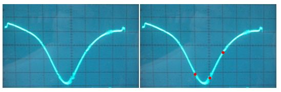
Figure 5. Filter response of ratio detector without stabilizing capacitor C2. Right figure shows filter response with added markers. Left figure shows that sideway markers are at different heights and peak of the filter is off centered.
The markers are expected to show a flat-top curve that ensures that the IF frequency remains constant with minor frequency deviation. The imbalance of the markers in figure 5 result from a tradeoff between obtaining a well-shaped curve and balancing the markers. I discussed this trade-off with Joe Sousa and we observed balancing the markers would cause the right end of the curve to be much lower than the left end. This resulted in major distortion of the shape of the filter and a lower amplitude. We decided on unbalanced markers but a better-shaped curve.
| STEP 2 SETTINGS | AM-FM Stereo Analyzer Sencore SG165 To Scope –> Phono-to-BNC adapter to BNC oscilloscope directly to CH2 All signal –> BNC to alligator to the radio (input) through 0.01uF dummy antenna. Analog Oscilloscope Ch1 –> Test probe to radio test point B Ch2–> To Stereo Analyzer “To Scope” |
` The input at the radio is left at the same place that in step 1, the input of the FM mixer. We reconnect the stabilizer capacitor C2. We adjust the secondary of the transformer at the detector A7 for symmetry of the crossover on the center of the 10.7 MHz frequency and straightness of the lines between the markers. We retouch the primary of the transformer A8 slightly for maximum amplitude of the lines. Figure 6 shows the curve of the output voltage vs the instantaneous intermediate frequency obtained on the Granco 720.

Figure 6. (Left) Linear response of radio detector with stabilizer capacitor. (Right) linear response between markers. Note that crossover overlaps with the middle marker characteristic of proper alignment.
The linearity of the curve in Figure 6 is a measure of the quality of the audio frequency output of the detector. Therefore, the Granco 720 radio has excellent linear response within its deviation range.
| STEP 3 SETTINGS | AM-FM Stereo Analyzer Sencore SG165 To Scope –> Phono-to-BNC adapter to BNC oscilloscope directly to CH2 All signal –> BNC to alligator to the radio (input) and ground through 39ohms Analog Oscilloscope Ch1 –> Test probe to radio test point B Ch2–> To Stereo Analyzer “To Scope” |
The output of this RF IF alignment is a DC level on the scope. We adjust the trimmers at the FM oscillator A12, A13 for maximum amplitude while the radio is tuned to 108MHz. We also adjust the oscillator coils L2 and L3 for maximum amplitude while the radio is tuned to 88MHz.
After properly tuning the radio, we evaluated the performance with measurements.
5. MEASUREMENTS
I measured three parameters to evaluate radio’s performance: capacitor leaking current, tubes DC bias and the AM audio frequency response.
5.1 LEAKAGE OF CAPACITORS
I analyzed the characteristics of four capacitors, taken from classmates’ radios [10]. I used a M3 Digital LCR Meter to measure ESR, capacitance, and dissipation factor; and a Heathkit Capacitor Checker Model IT-11 with a ammeter to check for leakage current. Table 3 and Table 4 show the obtained readings.
Table 3. Readings of presence of leakage, equivalent series resistance (ESR) and dissipation factor for four capacitors by type and voltage rating.
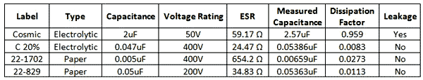
Table 4. Readings of leakage current for voltage applied and presence of leakage eye of four capacitors
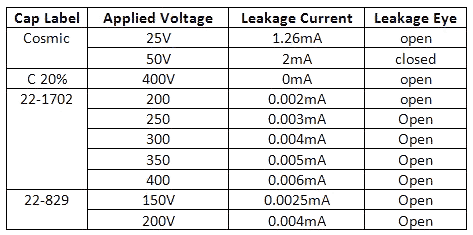
It is interesting to note that only one of the measured capacitors leaked. This is impressive considering that these capacitors are about fifty years old and the manufacturing techniques of the time.
5.2 DC BIAS MEASUREMENTS
Following the change of resistor R22, I expected a change on DC bias of the radio. Also, I measured the DC bias to check for proper DC characteristics. The readings are summarized in Table 5.
Table 5. Comparison of measured of DC bias vs. the expected DC bias according to radio schematic by tube and by pin number.

The DC bias at pin 1 V3 required a different measurement technique. All other measurements were taken with a digital multimeter. V3 pin 1 is the grid of the AM pentagrid converter. I measured this voltage by using an oscilloscope.
5.3 AM AUDIO FREQUENCY RESPONSE
The most important measurement of the audio performance of the radio is the audio frequency response. I measured the AM audio frequency response because it requires a signal generator to produce AM modulated signal as opposed of more specialized equipment required for higher frequency FM modulated signals [10].
For this measurement, I used a 455kHz carrier with 50% AM modulation in the audio frequency range from 20Hz to 20kHz. The -3dB points were found at 20Hz and 3400Hz and a flat response between 50Hz and below 1000kHz. This result show that the Granco 720 radio has a poor audio response at higher audio frequencies. The results are summarized in Figure 7.

Figure 7. Frequency response of radio Granco 720. -3dB points were found at 20Hz and 3400Hz with a mostly flat response between 20Hz and 3400Hz.
A fun experiment for audio response was to cascade two signal generators to create a sweep of audible frequencies modulated in AM. A first signal generator was set to produce a 5V sine wave with frequency sweep between 20Hz and 20kHz. This sine wave was fed into a second signal generator through the “AM Modulation In” BNC in the back panel. The second signal generator was set to produce a 455kHz carrier sine wave with external modulation. The result was an output AM modulated wave with variable modulation frequencies in the audio range. I fed that signal to the input of the AM converter with a dummy antenna and listened to the output. I heard the response from the lower frequencies up to the higher frequencies. I did an FFT of the output signal on the digital scope to observe the decrease in amplitude of the signal for each frequency. Figure 8 shows a screenshot of the oscilloscope.
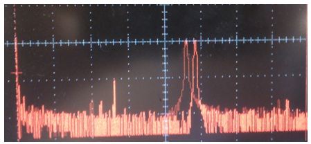
Figure 8. FFT in digital oscilloscope for a AM modulated signal swept between 20Hz and 20kHz. The peaks show the time progression of the sweep.
This was a fun experiment because I could see the real time frequency response of the radio, even though no meaningful quantitative measurements were taken.
The next section will discuss some of the errors and accidents that occurred during radio restoration.
6. ERROR ANALYSIS
Restoring a radio for the first time was a meaningful learning experience. The mistakes we made served to learn more about the section of radio involved in said mistake. In this section, we will describe the accidents and errors encountered during repair and operation of the Granco 720 radio.
The speaker had two tears . These tears may have occurred when the radio was manipulated. I fixed the speaker by adding black nail polish to the tears, keeping the surfaces together. Also, I added a cardboard protective screen over the speaker to prevent future accidents.
After replacing the 50pF capacitor broken in two and tuning the AM, the radio did not detect any FM stations. This 50pF capacitor was located at a hard-to-reach area between the back panel and a tube. Close examination to the signal path following with a 108MHz test signal revealed that there was a gain of 3 after all the IF amplifier stages, much lower than expected. The frequency of the signal did not follow a variation of frequency at the signal generator. I tested the capacitor leads for continuity and one lead had continuity to ground. After taking the tube out and bending back the panel to make the area more accessible, I saw that I had connected the 50pF capacitor following the wiring of C3 instead of the wiring of C5 (see below). When I had changed the broken capacitor, I had seen continuity to ground in C5 through L1, which I interpreted as the wiring in C3. Thus, when I changed the broken capacitor, the FM signal path was open. I concluded that the 108MHz reading was in fact circuit oscillations. I learned to pay attention to continuity through inductors in addition to direct connections and to make parts more visible before repairs.

Figure 9. Schematic of the FM antenna section of the radio. This shows that one lead of C5 and C3 will both have a continuity reading. Thus, they may be confused if continuity is the only criteria for identification. Visual inspection and a continuity reading with the FM antenna and the signal path can prevent this error.
We observed that the AM receiver detected the AM emissions of personal laptops. We learned to not test the AM band receiver with computers around.
Another error occurred while tuning the FM receiver. Even though I had properly tuned the receiver, I could not tune to any stations. Professor Roscoe observed that my radio was still connected through Variac at 70V. Increasing the voltage to 110V was enough to make the FM receiver work after it was retuned.
7. CONCLUSION
This paper documents the restoration of a Granco 720 to full function. We looked at the radio within the historical context of Granco Products, Inc. We examined the circuitry of the AM and FM receivers, discussed how we repaired the radio and made it electrically safer, and aligned it for best function. We evaluated the performance of the radio through measurements of DC bias, capacitor leakage and AM audio frequency response.
This was a fun project to work on. I enjoyed the opportunity to learn about the history radios and vacuum tubes. I documented this project in great detail for future reference.
8. REFERENCES
[1] Howard W. Sams & Co. Photofact Folder, Granco Model 720. Indianapolis, Indiana. Set 297, Folder 3. November 1955.
[2] Radio Museum “History of the radio manufacturer Granco Products, Inc; Long Island City (NY)”, [April 25, 2012]
[3] Radio Museum “Granco 720″, [April 25, 2012]
[4] Radio Museum “Granco Radio Products, Inc” , [April 25, 2012]
[5] T. Addams, Basic Electronic Series: Detector and Rectifier Circuits. Indianapolis: Howard, Sams & Co, 1961
[6] J. Sousa “Diagonal distortion in FM limiters” , [May 10, 2012]
[7] J. Sousa, Personal Communication. May 2012.
[8] S. Napolin. “High frequency tuners,” U.S. Patent 2831117, April 15, 1958
[9] S. Napolin. “Tuner chassis with integral shield and condenser plate,” U.S. Patent 3047824, July 31, 1962
[10] R. Roscoe, Personal Communication. April 2012.
[11] A. Ghirardi, J. Johnson, Radio and Television: Receiver Circuitry and Operation. New York: Holt Rinehart and Winston, 1961
Attachments:
- Granco720 signal paths (131 KB)
To thank the Author because you find the post helpful or well done.