grundig: 8058; Majestic Restoration
grundig: 8058; Majestic Restoration

Restoration of a Grundig Majestic 8058/USA
Due to the fact that this radio was determined for USA Export from Germany I decided to present the report on the restoration in English. Native speakers please apologize for my strange German-English wording.
Recently I got said model from a friend of our family. Her parents bought this radio in Paris 1958 when her father was stationed as GI there. Now her mother passed away recently and so I inherited the radio because she had heart about my collection.
All papers were enclosed and I did an upload here in RMorg of the Grundig diagram and the maintenance which was styled in the typical1950ies style.
The radio was in quite good condition because it was stored in the living room for the last 54 years despite the fact that it doesn’t work well in the last years. But the old lady did not find anybody who was able to repair a radio of the 50ies.
Disassembly
For the disassembly of the Chassis the record player has to be lifted. Take care, otherwise a damage of the glass scale could occur! To lift the chassis of the record player (here a Pertuum Ebner RexDeluxe) two rocking levers under the turntable have to be moved. The chassis of the record player may also be fixed by two screws under the two holes.
 The loudspeakers are connected to the radio by a multi-plug. For testing the radio on the work bench fortunately additional standard connecting sockets are on the backside of the chassis.
 It is quite difficult to place the chassis in a position that the parts are accessible. On the left side the rectifier is mounted, on the right side the coils for tone control and on the backside the ferrite antenna is placed. At last I put it upside down on the workbench.

 Scale
Scale
The scale can be removed easily and fortunately the printing is stable and can be cleaned with a damp cloth. In the tone control scale the red rubber between the indicators was brittle and missing. It was substituted by a red yarn straightened by a spring.


Chassis
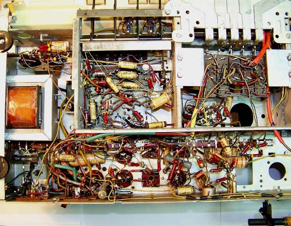
The picture shows the chassis of 8058. You see the typical parts of 1958 and it is obvious that there was no repair so far. Everything looks original. It is my target that after restoration this should not be changed. A restoration should always be done with original parts which is unfortunately only possible in exemptions. If new parts have to be used the changes should always be reversible. That means old parts remain in the set or are added to the set in a small plastic bag after restoration. The purpose of the restoration should also be considered beforehand. Do you want to use the radio daily or do you only want to show the performance occasionally ? In the first case it is more a repair than a restoration and more parts have to be replaced to guarantee a reliable and safe function of the set.
 The first measurements of the anode voltage of the set showed that the selenium rectifier has got a high internal resistance as usual. This is a typical failure of these rectifiers. I installed a modern one. Sometimes it may be necessary to add a serial resistor of approx. 100 Ohm to get the right voltages because the modern rectifiers have a much lower internal resistance than the old ones. Here 70 Ohm has been sufficient. For the first time I increased the power supply slowly using a variable Transformer. The old electrolytic condensers need a little time for formation and building up an isolating coating on the electrodes again. Here the electrolytics are still in good shape and work well.
As visible on the photo a lot of ERO paper condensers have been used beside of more reliable polyester film condensers. The ERO paper condensers always have some leakage. These condensers may have a leakage current after 50 years in the range of 0,1-10 µA at the intended voltage. In most cases this is acceptable beside of some critical uses e.g. coupling condensers between two valves.

In this case I checked and replaced the coupling condensers at the grids of the EL 95 push-pull amplifier. The red arrows on the picture show the substitutes. Left a visible version and on the right side invisible. The old condensers remained in the set and due to that the restoration is reversible.
I hate the usual total “de-capping” of sets and prefer an analysis of the voltage at the electrodes of the valves to identify absolute unavoidable replacement of parts. E.g. the anode voltage of ECC83 was measured too low. The reason was simply a leakage in C 86 (I refer to the Grundig original diagram uploaded to the model) which causes a positive grid voltage and an increased anode current resulting in a high voltage drop at R74. The grid leakage resistor R67 is 10 MOhm and due to that a leakage of a few µA in C86 causes a change in the grid voltage level.
A little confusion was caused measuring the grid voltage of ECC81. Here an obvious misprint in the diagram says “-0,9 V” grid voltage. I measured at the grid +12 V and + 17 V at the cathode which is a difference of 5 V and is in line with the theoretical data for the ECC 81. C 64 at the grid was o.k. and additionally not connected to any voltage source which could increase voltage at the grid in case of a leakage. The grid is connected to the cathode with a 1,2 MOhm resistor and measuring 12 V at the grid makes sense.
The first tests of the set showed that it is very sensitive but the bass response was not good and distorted. After some time additionally the set became insensitive on all wave bands. Measurements at the EBF 89 show a g2-voltage of only 4 V instead of required 84/94 V ! I expected a possible failure in R17 (56 kOhm, could have become higher) or in C 49 (6,8 nF could have a leak current to chassis). At the end it turned out that g2 of the valve had a shortage to the cathode. After replacement of the EBF 89 the set worked well beside the distortion.
While checking the set I discovered a critical point. The wire from the AM-antenna connector to the Hf -coils is routed through a hole in the chassis around the on-off switch. The switch moves forth and back and damages the isolation of the wire. This may cause problems with AM waveband reception.


Loudspeakers

 The set has five loudspeakers and should have a very good performance. Bass 25 cm diameter, two middle tone loudspeaker and two electrostatic high tone loudspeaker. The bass response remained distorted despite a proper alignment of the electrical data of the set. After disassembly o
 f the bass loudspeaker it turned out that the cone was no more fixed to the chassis. A polyurethane foam sheet has been used to fix the cone to the chassis. Such a sheet has the advantage that the cone can move freely without being hindered significantly which is important for good bass response. Same problem can be seen here . Consequently the membrane and the moving coil touched the chassis and cause distortion.
I got a polyurethane foam sheet from a do-it-yourself shop, thickness 3 mm and cut a ring out of it. The picture showed the remaining inner part of the ring (Grundig-8058-PU-foam1). The old brittle PU foam was carefully removed. Now the moving coil was fixed in its slit with paper stripes and the PU foam sheet was glued to the cone and the chassis with a special glue for foamed materials (Grundig-8058-Basslautspr3). Afterwards an additional stripe was glued to the chassis which tightens the loudspeaker to the cabinet. On the picture this stripe is of darker foam and approx. 5 mm thick (Grundig-8058-Basslautspr2). The paper stripes were removed after the glue was dry and the loudspeaker works well again.


Record Player
The record player is connected to the radio by two banana plugs. Use the lower two contacts of the 3-hole socket. The middle one is connected to the chassis, the lower one to a pre-amplifier for the record player. The upper contact directly is connected to the ECC 81 without pre-amplifying. By the way: The German version of the set does not have the additional pre-amplifier and is using a EC 92 instead of the ECC 81.
 The motor has to be cleaned and oiled. To remove the system is very difficult. I tried to pull it as usual out of the pick-up arm at point (2) but failed. I did not want to use too much force to avoid crack of the arm. So I dismantled the head of the arm by removing the screw (see picture) and unsolder the wires (1). Then I removed the carriage of the pick-up system by removing two screws hidden under the system. (I hope there is a place in hell where engineers who designed such a thing have to work the whole day with their devices…) Now I could remove the system. It can be turned in two directions for “normal” grove record (Shellac) and “micro” grove records (vinyl) (3). The vinyl needle has to be substituted and I am still looking for one. A good advice: Clean the contacts (4) of the system and the carrier. They are silver plated and became dark and had contact failures. Maybe there is an easier way to remove the system, but as explained I feared to crack the arm.
The weight of the pick-up can be adjusted by a screw that adjusts the counter force of a spring at the bottom of the arm. The rubber belts of the turntable drive are still ok and the  performance for shellac records is ok. I did not change the belt because they are difficult to get and I do not intend to use the player permanently.
End
The radio has a very good performance and is very sensitive on all wavebands. For use today it has the advantage of having a “modern” FM waveband of 88 – 108 Mc. In Germany radios of that time had only 8 -100 Mc today also 88 – 108 Mc.
To thank the Author because you find the post helpful or well done.
Excellent article, came in handy for me
I have just today (Feb 5th, 2012) completed my own Grundig 8058 restoration.
Rüdiger Walz:
My experience mirrored yours very closely, but I decided to completely change all capacitors. I did save the old capacitors for posterity.
The speaker repair you mentioned was very challenging for me. it works great now.
Question: On the MULTISONIC on my instrument, the highest treble tone control on mine will only go slightly above the horizon and I do not get full range of the control like the other adjusters.
This control has a cable that is connected to some device.
Do you get full range control of the highest treble of the multisonic?
Can you tell me what the cable and device are for?
Can I adjust this cable control for more treble?
To thank the Author because you find the post helpful or well done.
Multisonic Control
Yes my control for the highest tremble tone also only goes slightly above the horizon. This seem to be o.k. It is coupled mit a bandwith regulation in one of the IF transformers by a cable. Here two coils are moved close or apart. The bandwith of the transformer is consequently changed and the tremble is cut or not.
In RMorg should be some explanations on that. Choose "bandwith" as key word in "SEARCH".
Best regards
Rüdiger Walz
To thank the Author because you find the post helpful or well done.
Help with a 7028 restoration
To thank the Author because you find the post helpful or well done.
grundig: 8058; Majestic Restoration

I need to take the picup arm off, how can I do that?
To thank the Author because you find the post helpful or well done.