katzen: Midget Lucille (KATZENSTEIN & KEENE, N.Y. USA)
katzen: Midget Lucille (KATZENSTEIN & KEENE, N.Y. USA)

Hi Rmorg, who can dive in and help?
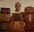
I own this very nice midget radio, Model LUCILLE, from KATZENSTEIN & KEENE, New York, USA
http://www.radiomuseum.org/r/katzen_lucille.html
Today I could repair it, but have replaced the missing power cord with integrated resistor by a 125 Ohms resistor, according to my calculation, for a main voltage of 110V. So my first question: is it still possible to buy a replacement power cord, like the original? If not, who has a solution? On my side, I have integrated the replacement resistor on the chassis. Without the cabinet, every thing is OK, but I am effraid about the additional heat generation when the wood cabinet will be mounted (risk of damage)...
And by the way, does somebody know more about this make? I could find nothing with Google. Has somebody the schematic? The first filtering capacitor was 32µF, the second 16µF, is this OK? (those in place were not the original).
Thanks a lot for sharing info and tricks,
Christian ADAM
To thank the Author because you find the post helpful or well done.
Quick and dirty

There is a simple solution - at least until you get such a cord I'm looking for since many years ;-)
You calculate for a condenser in series.
I can imagine that in the USA there is such cable since it is rather common to drop voltage this way for the heaters in series on small sets.
In France you see some resistors on the side of the plug for tiny tube radios for the same case.
The solution with a C is simple but you have to know that you still get the high voltage but the parts get only the currant needed and are happy with that. A radio is not the same as a lamp but specially if it is for the heaters only it is ...in this respect.
To thank the Author because you find the post helpful or well done.
Line cord resistor

Dear Christian and Ernst,
Although line cord resistors were fairly common at one time in U.S. radios, I have never heard of anyone finding a modern source for replacement cords with the integrated resistor. By the 1940s, these types of line cords were viewed as fire hazards and no longer used. Today they are often referred to as "curtain burners."
These days they are generally replaced with either a power resistor or a series capacitor (as Ernst suggested). A capacitor has the advantage of no appreciable heat generation.
Best regards,
Tom
To thank the Author because you find the post helpful or well done.
Clever solution!
Dear Ernst and Tom,
Yesterday I posted the question, today I am lucky: I have a clever answer from everywhere in the world (Radiomuseum.org makes globalisation nice). Yes a capacitor should be a good way to avoid heat generation; I came to a 11,5µF value. I guess a coil could also be used (something like 1H).
Thank you both for jumping in and you especially Ernst, for having created this Radio-Solution site
Best regards from Colmar, France
Christian
To thank the Author because you find the post helpful or well done.
Another possibility

Hi Christian,
If the line cord resistance is for the heaters only then another possibility is to use a combination of a rectifier & a resistor. This may be easier than fitting a large capacitor. The difficulty is calculating the value of resistor. The rectifier will half the power but not the voltage. Some power will still be dissipated in the resistor, but it will be much less than without the rectifier.
Regards
Keith
To thank the Author because you find the post helpful or well done.
Also an interesting idea
Thank you Keith,
Very interesting. May I propose here a way to determine this drop resistor?
My set of tubes needs 2x25 + 3x6,3V = 69V. In addition a 6,3V 0,3A dial lamp in parallel with a 25 Ohms resistor will have 3,5 V drop under the 0,3A. So I need to feed this heater line with 72,5V AC under 0,3A.
Introducing a diode will half the power. To keep this heater power constant, we need now to feed all the line with a voltage multipied by 1,414 (because power varies like the voltage power 2). So if the main is now 102,5V AC, the heater line will be correctly powered. But in my case the radio is designed for a 110V main voltage. We need a small drop resistor, as you say. Let's determine this resistor using the reverse way:
A 110V AC main with a serial diode will perfectly feed a 110 / 1,414 = 77,8V heater line. As seen my line needs 72,5V so a drop resistor is needed. Drop voltage is 5,3 V under 0,3 A, means a resitor of 17,66 Ohms, let's say 18 Ohms. This drop resistor will dissipate 5,3²/ 18 = 1,56W. That's acceptable.
In comparison, without a diode I have currently a 125 Ohms drop resistor dissipating 11,25 W = 7 times more. This is not acceptable in a small radio.
So, seems that your proposal is very adequate to this situation. Till now this is only theoretical calculation work. Who would like to add a comment before the experimentation?
Thank you,
Christian
PS: in the mean time, I got another very nice answer from Mr. ROSCHY, explaining how very simple changes in the wiring will allow to adapt these kind of 110 -115V midget radios to our today european standard of 230V AC. I've asked him to put this explanation on line so that everybody can benefit from this other solution :-)
To thank the Author because you find the post helpful or well done.
3 replacement solutions tested. Radio works fine now ...
Hi Rmorg,
During this amount of time I could test 2 other proposed solutions: the capacitor and the diode in serial wiring with a small drop resistor (see above).
First photo shows the old line resistor power cord and the 3 tested replacement solutions for a main of 110V AC. The big resistor correspond to the first tested solution, a 125 Ohm drop resistor dissipating 11,3 W. Not acceptable in this small midget housing, except if you like seeing firemans in action!
After I checked the capacitor solution. Calculation using the Fresnel diagram leaded to a 11,5 µF submitted to 90 V AC. So a 400V or more non polarized capacitor is highly recommended. It works, simply it takes space (not so smart). But the capacitor don't warm up because it's current is in quadrature.
I tested also the last diode + small drop resistor solution (photo 2) according to my calculations here above. Here also the radio works perfectly. In this case don't use a controller to check voltages or currents: the indication is fully wrong (except if it is a true rms controller). In this case you may verify that everything is OK using the following rule: if you power the device with only half a sinus wave because of the diode, then the amplitude of the half sinus must be twice of the rms voltage value needed with the standard sinus AC.
This is illustrated in photo 3: the heater + dial chain needs 72,5V rms in normal use. For the half sinus, we need an amplitude of 145V. This is shown on the photo: the oscilloscope caliper is 50V /div.
This solution is the nicest under the chassis and I stayed with this last one. The power dissipated in the resistor is 1,6W, let's say acceptable. The only cons is that the use of classical multi meters is not recommended!
Two last comments:
1) on photo 1 the capacitor has 22 µF: I had no nice 11,5µF available (needs several connected together). But it gives a good indication of the size...
2) the best is to connect the diode in the opposite way as the valve, to get main current shared in both directions.
Thanks to all the contributors to this forum. If colleagues are interested, I can help and share theoretical calculations to determine the capacitors and the resistors,
Best regards from France,
Christian ADAM
Attachments:- Original cord and 3 replacement solutions (63 KB)
- View of replacement resistor and diode 1N4007 (81 KB)
- Heater chain caliper 50V (74 KB)
To thank the Author because you find the post helpful or well done.
Resistance Line Cord Replacement
Hello, All!
I've got several "curtain burner" radios from the early thirties. I've found a website that has calculations for getting the correct replacements and it works well. I think the size of the capacitor you were having to use is a bit excessive, too.
Here's the site: http://www.electronixandmore.com/articles/calc.html
I use the Solen capacitors that are a little smaller than the one in your picture. You can get them directly from the factory, too.
Best Regards,
Robin
To thank the Author because you find the post helpful or well done.
It was not the right capacitor on the photo ...
Hi Robin,
Thanks for jumping in,
On the photo the capacitor is a 22µF. Just to have a nice one on the picture. But in the real life my calculations and trials gave 11,5µF...
Best regards from France,
Christian
To thank the Author because you find the post helpful or well done.