marconi: 702;
? marconi: 702;
Count of Thanks: 11
I am trying to upload pictures for the Marconiphone 702 mirror-lid television receiver but the upload does not start. I have tried on several occasions on different days but have not succeeded. I use the "Uploads & Questions" button on the 702 page, fill in the form and hit "upload" but radiomuseum does not seem to accept my file. What am I doing wrong?
Brian Cuff
To thank the Author because you find the post helpful or well done.
Uploads fail
Make sure that they are jpg format (must end in .jpg) and don't exceed file size, width or height limits.
Make sure you have all needed Javascripts enabled if you are using any script, advert or virus blockers.
Make sure you are logged in.
Make sure you PICK
(_) Picture from another source.
(+) Picture from my own collection.
Also you MUST choose the Content and Quality
Browse for File
Click Send
It works for me on Windows and on Linux, using Firefox Browser.
You are using the correct menu.
To thank the Author because you find the post helpful or well done.
Further Information Regarding the Marconi 702

Marconiphone 702
In 1934 the Marconi-EMI Television Company Ltd was formed bringing together the vision transmitter technologies of the Marconi Company with the television studio equipment and receiver technologies of the EMI Company. It was this company that provided the technology for Britain's television service in the years from 1936 through to the switch-off of the 405 line transmissions in the early 1980s.
The very first dedicated television receivers developed by this alliance were the HMV model 901 and the Marconi model 702. These sets were essentially identical but had differences in the veneering of the cabinet and the shape of the speaker grill so as to appeal to traditional customer loyalties for the two brands. The same design of television circuitry was also incorporated into a number of other sets carrying the HMV and Marconi names that included radios and gramophones.
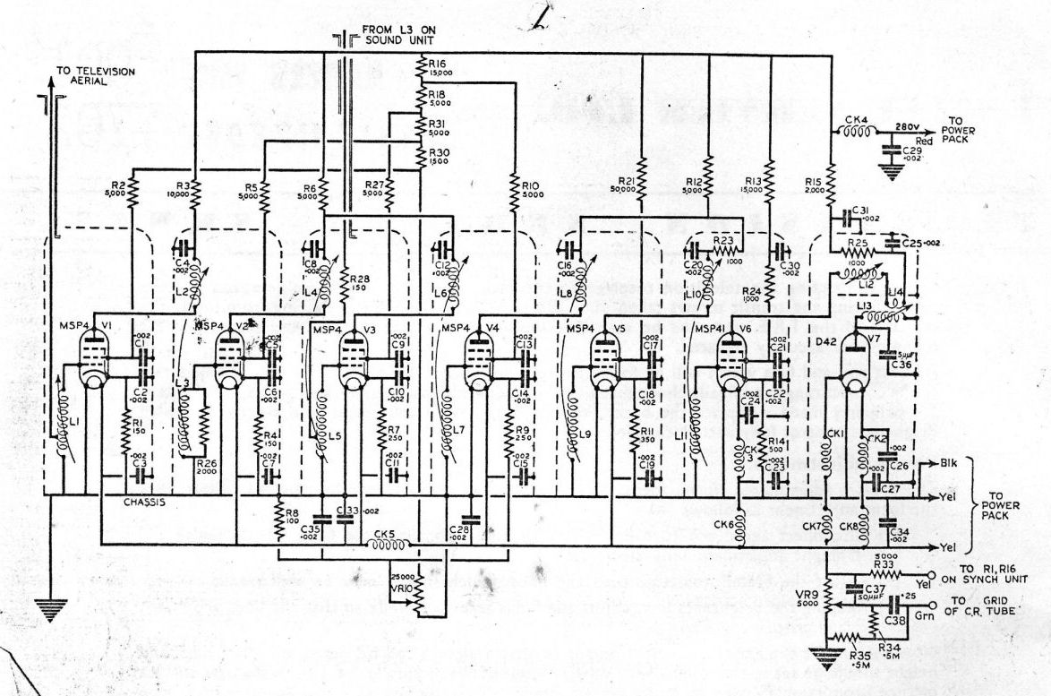
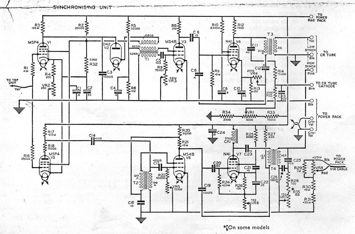
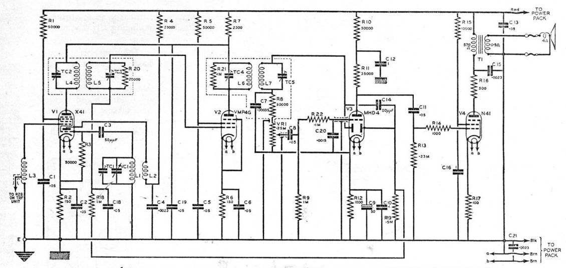
At this time there was only one television channel and one transmitting station. This set is designed with a straight (TRF) vision receiver tuned to 45 MHz. and consists of six RF pentodes and a diode detector. These are contained in seven screening cans. There is no video amplifier. The detector connects directly to the CRT. On the opposite side of the CRT are the synch separator and line and frame timebases and on the floor of the cabinet is the power supply chassis. The 5000 volt supply for the CRT final anode is generated from a step up transformer from the mains and this and the EHT rectifier are located below the timebase chassis in a metal box behind the HT rectifiers. The sound receiver is a superhetrodyne tuned to 41.5MHz and is located between the loud speaker and the CRT. It shares the first two RF stages with the vision receiver and its RF connection is taken between the second and third cans from the top.
TRF Section
Synch Unit (Timebases)
Sound Receiver
Power Supply

Attachments
- HMV901 TRF (174 KB)
- HMV901 Sync (166 KB)
- HMV901 Sound (96 KB)
- HMV901 Power Supply (99 KB)
Block Diagram

Service Information


To thank the Author because you find the post helpful or well done.