mediator: Mediator 1502U-10, Power Resistor and more
mediator: Mediator 1502U-10, Power Resistor and more

This article is aimed at beginners who, like me, take the first steps in the restoration and repair of tubes radios and they have a minimum theoretical knowledge of radio technic.
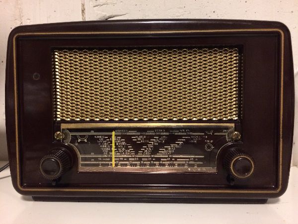
The story started when I received a small Mediator 1502U radio, which I immediately turned on to see if and how it worked. When I turned on the radio for the first time, with a test bulb of 100W and then without it, everything worked well. The next day when I turned on the radio again I saw smoke coming out of the radio and a resistor incandescent: I still have not understood what it happened.
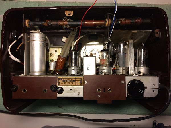
When I opened the radio, in the burned area, there were some things that I could not understand and reconcile between what I was seeing in the radio and what was instead indicated in the wiring diagram.
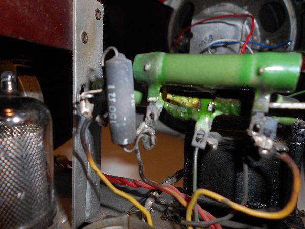
There was something a bit strange among the power resistors, it were too many, I could not able to determine their values and, unfortunately, I did not find in Rmorg and everywhere a picture that shows the internal of the radio for checking, so to clarify my ideas, I schematized what I saw on the radio and how it was originally intended.
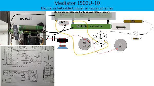
Thanks to this, I found that the lack of correspondence between the radio and the wiring diagram, was due to the fact that in a previous repair, concerning the burned resistor R2 + R3 + R4 (180 + 200 + 430 Ohm), which was not been disassembled to be used as a support for the separate assembling of the new two R2 of 150 Ohm and R3 + R4 of probably 200 + 430 Ohm, unknown Watt.
Original 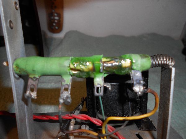 Old repair
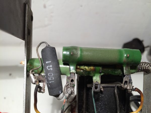
So I asked for help in the RMorg Forum (Power resistor) to know the power of the burned resistor, and Marc Gianella that at this point, I can call "the friend" Marc, listened to my help request and he has followed me from the start to the end of this experience, also through direct contacts, giving me many good advice and even for free electronic components, to get back into operation the radio.
Furthermore I have to mention also all the explanations he gave me, much more than I could understand, but that, to try to keep up with him, have stimulated in me the desire to document me, to better understand what we were doing as, as I said, it was the first time I faced these problems.
First of all, Marc advised me to think about security in various terms:
- MY SAFETY, since the radio is a model without transformer and for this reason it is very dangerous to work as it is directly connected to the electricity grid, so first of all he told me to equip me at least with an isolation transformer ( trenntransformator )
- OF THE RADIO, using a test bulb to prevent possible short circuits could cause damage to the radio ( vorschaltlampe ). Furthermore, to protect the output transformer the capacitor C30 instead to be connected to the chassis has been connected to the output transformer.
- OF THE PERIPHERAL DEVICES connections (turntables, MP3 players, iPhone), replacing some capacitors with those of type X or Y: the capacitor on the power line with one of type X (C32), while for the connections with the outside, replace the existing paper capacitors with Y-type capacitors (C3, C34, C35, C36).
Before 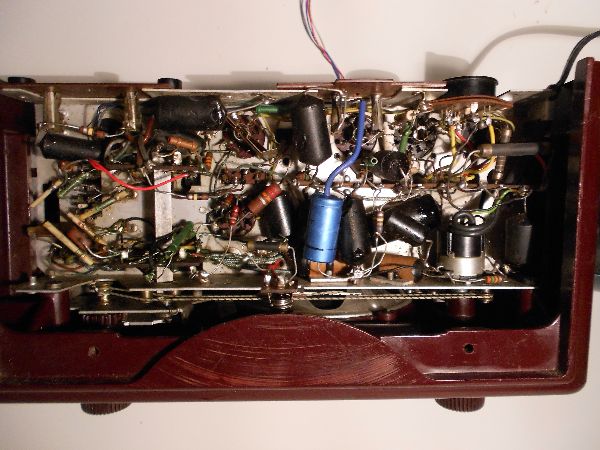 After
After 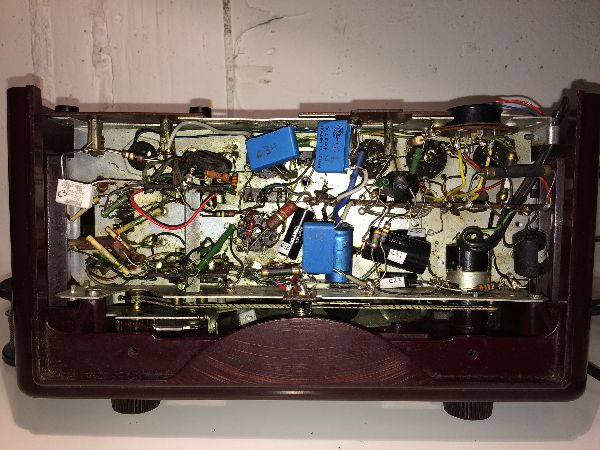
Performed these preliminary operations, we worked to put the radio back into operation, so we replaced the fall resistor which, as I said at the beginning, was burnt in my hands (R3 + R4) with a resistor of 680 Ohm 25W and all others "paper" capacitors probably at a loss, (C12, C20, C27, C29, C30, C31, C38)
Replaced parts 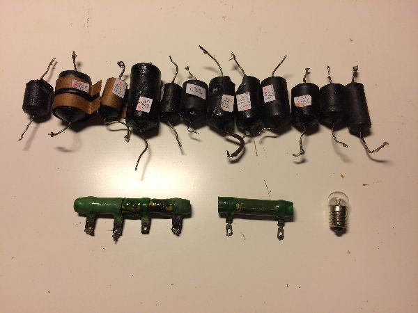
At this point we made some measurements of the resistors to determine the defective ones and (R16, R21) were replaced

 .
.
After these operations the radio worked again !!! but it heated a lot that was because the tensions were generally too high (on average + 15%) so probably we needed to readjust the values of the fall resistors R2 that Marc has calculated around 280 Ohm.
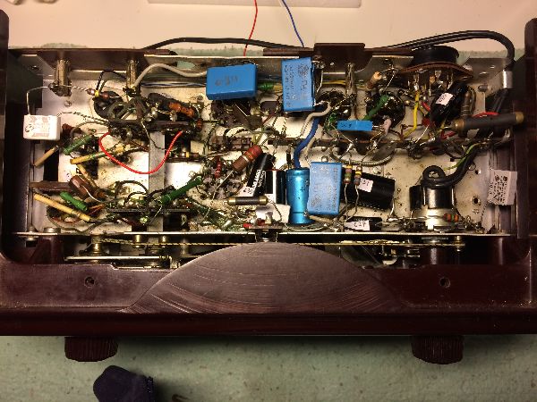
In fact, after some attempts with different resistors, adding a resistor of 150 Ohm 11W to R2, the measured voltages corresponded to those declared in the wiring diagram and finally I could close the radio again because the work was finished
At the end 
I do hope that this experience of mine can help others like me who want to dedicate themselves to these activities
Still many thanks to Marc for the support during all these activities and many thanks for your attention.
Roberto Licandro
To thank the Author because you find the post helpful or well done.
mediator: Mediator 1502U-10, Power Resistor and more

Hello Roberto,
Your radio has the same tube set and cabinet as the Siera SA1001U (like Mediator a submark of Philips). Unfortunately I do not have a schematic of the Siera or Mediator model available. However, I recommend you to use the schematic of the Philips BX335U, which has a similar cabinet as your Mediator 1502, the same tube set and a very similar chassis.
See model page Philips BX335U.
Regards,
Gidi
To thank the Author because you find the post helpful or well done.
mediator: Mediator 1502U-10, Power Resistor and more
Hello Gidi,
many thanks for your information the photos of the chassis of Philips BX335U confirms the correctness of my supposition about the orginal cablage of the power resistors.
Regards
Roberto
To thank the Author because you find the post helpful or well done.