phonola: 5512;
? phonola: 5512;

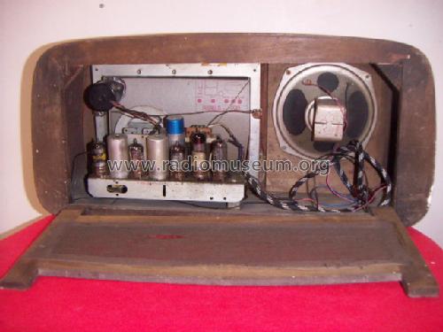
Looking at the photograph of the back of the radio, I do not think the valves you see (the Rimlock)
match those of the presented scheme (European series of tubes).
What model is reported on the label that is visible and showing the positioning of the valves?
To thank the Author because you find the post helpful or well done.
1952
Why would a 1952 set use ECH4 EF9 EBC3 EL6 EM4 WE53 though which are 1930s/1940 tubes and after WWII Octal would be more likely alternative to Rimlock?
Something is in error somewhere! But perhaps not.
I downloaded a Phonola 5512 schematic from elsewhere and it is
ECH41 EF41 EBC41 EM4 4699 AZ2
(poor quality scan but definitely that's what it is)
But curiously the EM4, 4699 (=EL6) AZ2 (=WE53) ARE the Europe side contact base P (P8A).
so perhaps it's a 1940 design gradually updated to rimlock? Certainly I can't see EL6/4699 or WE53/AZ2 but the magic eye does look like it has the side contact base.
I think I have heard of US sets with loctal-8 (Loktal) fitted in later production in place of Octal.
UPDATE
I found a Phonola 5512 on eBay and it is ECH41 EF41 EBC41 EM4 4699 AZ2, the uploaded chassis is completely different
Reduced size & edited versions of schematic and pictures found (original quality too poor)


Very similar front, but Magic eye in different location.


So the tube line up AND the model photos seem wrong!
I suspect there is a range of models based on a "5512" generic design. Where is the Mains transformer on the uploaded chassis Photo?
To thank the Author because you find the post helpful or well done.
Base model and revisions

The answer is quite simple looking at the RMorg archives. Phonola made several updated variants of its 5512 base model, dated 1952: same shape, but updated chassis. The tube line-up in the early model included the European side contact based tubes, ECH4 EF9 EBC3 EL6 EM4 WE53.
Then we find other models:
-5512A, about 1953, tubes: ECH42 EF41 EBC41 4699 EM4 AZ2
-5512B, about 1954, tubes: ECH42 EF41 EBC41 EL6 or 4699 EM4 AZ2
-5512C, about 1953, tubes: ECH42 EF41 EBC41 4699 EM4 AZ2
-5512D, about 1953, tubes: ECH42 EF41 EBC41 4699 EM4 AZ2
Now the date of each model can be wrong, since the D should be the latest one, but the tube line-up for each model is correct.
Simply the pictures are loaded to the wrong models. The pictures loaded to the 5512 base model are related to one of the later revisions. But even the pictures loaded by Guido to the 5512A are in the wrong place, since they refer to the 5512 base model.
Emilio
To thank the Author because you find the post helpful or well done.
Tubes type in the 5512A
I am not so sure about the tubes set used in the phonola 5512A model (and 5517 chassis too) because the radio that I have (5512A Phono) uses all European lateral contacts tubes i.e. ECH4 EF9 EBC3 EL6 EM4 AZ2 (or WE53); please visit Radiomuseum for this model and see the photos that I have uploaded.
I would like point out, that the first time that the Phonola 5512 and 5512A schematics were published was in the Radiolibro 12a edition, 1951, Hoepli editor, thus the year of first production of these models could not be ascribed after that date.
Finally, there is no surprise for the presence of old tube type (obsolete) in the radios built in Italy just after the end of the Second Word War.
Attachments:
- Phonola 5512A and 5517 chassis (32 KB)
To thank the Author because you find the post helpful or well done.
Confirmations
Thanks Emilio for pointing out the other models.
So is the uploaded photos a 5512 at all as the rectifier and audio out are Rimlock?
Or is there an 5512-E?
To thank the Author because you find the post helpful or well done.
The many variants of Phonola models
Michael,
Probably I am not the right person to clear all the confusion existing in those years. Phonola was just a brand of Italian Philips and built either radios badged Phonola and Philips. Due to customs fees, they had to use components manufactured in Italy whenever possible. European side contact based tubes, as EL6 or 4699, EM4 or AZ1 were currently produced in their Monza plant. To move to newer tubes, they had to wait that their productions, once stabilized in Holland or in Germany, were gradually spreaded to Italy.
It is quite difficult to precisely date either the radio models and the tubes. Side-contact Eropean tubes were in production even before WWII. Rimlock based types, as the ECH42 or the EF41, can be dated around the late '940s: certainly they were in production in Italy in the eraly fifties. More or less in the same years, Philips Holland, and maybe Valvo and Mullard, had already introduced noval types, as the ECH81. Probably their production was delayed in Italy for a short while. And anyway the use of old style magic eyes was common even in Germany well in the late '950s. You can find a lot of Grundig radios with EM34/EM35 magic eyes, the octal equivalent of EM4. Give a look at the many radio models listed for using these tubes even in the sixties!
But even the dates of the Phonola 5512 models, and the same model names, are not sure. I have an original Phonola schematic diagram that covers models 5511, 5512 and 5517, with all side-contact tubes. Another diagram covers the models 5512A and 5512B, both with mixed rimlock and side-contacts tubes. Different codes may refer to the cabinet, table or console, and to the presence of a turntable. Anyway I do not know the exact date when each model was introduced.
We must assume that the tube line-up of each model was the more advanced commercially available here in Italy at the moment.
Emilio
To thank the Author because you find the post helpful or well done.
Phonola and Philips
Emilio has rigth in telling that Phonola was just a brand of Italian Philips, but, if I am not going wrong, I remember that this happened in 1969. Please, give me same more time, and I will be more precise.
Guido.
To thank the Author because you find the post helpful or well done.
Here are the schematic diagrams of both
I am going to attach the schematic diagrams of two Phonola chassis printed from the CD 'Radio Italiane' Vol. 1, 1933 to 1953, by Mureddu and Atzeri. The material looks to be original. The first diagram covers the models 5511, 5512 and 5517. The legend on the right side also refers in brackets to a 5511A. The second one refers to 5512 A/B, 5517A and 5518. The two diagrams differ for the tube line-up, all side-contacts in the first one and mixed in the second one.
As usual, here in Italy there were a lot of models and a lot of confusion too.
BTW, I am not referring to the full ownership of Phonola by Philips, but to some kind of control that I remember since the late fifties or the very early sixties. As far as I remember, Phonola always used Philips components and even their dealers were the same.
Emilio
Attachments:
- Diagram of Phonola 5212 (166 KB)
- Diagram of Phonola 5212A/B (161 KB)
To thank the Author because you find the post helpful or well done.
Phonola
The Phonola history is at this Link
To thank the Author because you find the post helpful or well done.
Schematics
Dear Emilio,
What you are saying about schematics on CD is perfectly correct.
The point is (I have these CD version 2.5) that these diagrams cames from Ravalico literature (the "Radiolibro" or/and "Schemi di apparecchi Radio" both Hoepli Editor) as well most of those reported in Radiomuseum for these phonola models.
But if you look at the "Manuale del radiomeccanico" Vol. 3, page 197, G.B. Angeletti, Mosè Editor, you will find something different.
See
Attachments:
- Phonola diagrams 5511-5512 Phono and 5511A-5512A Phono-5517 (144 KB)
- Schema Phonola 5511-5512 Phono and 5511-5512A Fono-5517 -- Angeletti (144 KB)
- Diagrams_Phonola_5511-5512_Phono_and_5511-5512A_Fono-5517_Angelett (144 KB)
- Diagrams_Phonola_5511-5512_Phono_and_5511-5512A_Fono-5517 (144 KB)
To thank the Author because you find the post helpful or well done.
Wrong descriptions
Of course, the diagram above are inverted. Unfortunately, no way to edit them and to put them in the proper sequence. The editor cannot edit the legend of attachments.
Sorry, Emilio
To thank the Author because you find the post helpful or well done.
No way to cancel files
Yes, me too, I cannot delete the repeated files!
Guido.
To thank the Author because you find the post helpful or well done.
The usual confusion
Guido,
this is the usual confusion of sources here in Italy. The diagrams I attached look quite similar to Phonola original documentation. They also include in other pages the service notes and the tuning dial string layout.
This is one of the reason why I do not like Italian sets. The second one is given by the quality standards accepted for ANIE sets. The true excellence to kill users.
Emilio
To thank the Author because you find the post helpful or well done.
What is this Photo?
Dear Michael,
About the question of what kind of Phonola is showed in the uploaded photos, I suggest that it will be (probably) solved if a further picture, showing the radio label, will be uploaded.
Guido.
To thank the Author because you find the post helpful or well done.
Uploaded photos
I emailed the uploader asking just that. With (bad?) Italian translation via google also!
To thank the Author because you find the post helpful or well done.
5512?
The chassis of this radio (presented here as Phonola 5512) looks very similar to Phonola 5567.
Guido.
To thank the Author because you find the post helpful or well done.
Try in Italian Forum
Sorry Guido, but I cannot see the similarity. According to the tube line-up, the 5567 was a cheap set, without power transformer and with different tubes, designed to operate with series connected heaters.
In order to find an answer on the starting question, my best advice is to enter the same in the Italian Forum. Maybe that someone knows the Phonola production of those years and can tell how many variants of the 5512 were actually made.
Emilio
To thank the Author because you find the post helpful or well done.
which?
The original Model upload, not my upload does indeed look similar, all Rimlock and no visible mains transformer.
It's very like the 5567
The one uploaded here:
(by original upload to model, not the one in Forum Post which *IS* one of the 5512 versions
The one uploaded to 5567
To thank the Author because you find the post helpful or well done.
The intrigues of Phonola
Dear Emilio,
Thank you for the good idea to expose the case in the italian Forum.
What I was trying to say is that the photographs of the presented models in Radiomuseum (5512 & 5567) are very similar if not identical, not that the two models are the same.
About the transformerless Phonola 5567, I have not found literature supporting this feature, however diagrams (and the photos too) show that these radios have a power supply transformer (1-3) with a voltage changer on the top. The output transformer is under the chassis.
Guido.
1) Ravalico, D. E. (1960), Schemi di Apparecchi Radio, Vol. 2, Hoepli, Milano, pp. 240-241.
2) Angeletti, G. B., Reprint of Il Manuale del Radiomeccanico, Vol. 3, Mosè Edizioni, pp. 210-211.
3) See related model in Radiomuseum.
To thank the Author because you find the post helpful or well done.
Look at the transformer
Dear Michael,
in the photos that you have posted, the power supply transformer is visible just behind the rectifier and the output stage tubes, (chassis's back view, rigth side)
Guido.
To thank the Author because you find the post helpful or well done.
hidden audio TX
I thought that was the Audio transformer and the set used a "dropper" cable or something!
It's a smaller than normal mains transformer.
Well there is no doubt that the 5512 and 5567 are completely different models and that Alessandro Arrigoni has probably uploaded photos of a 5567 or something similar. There isn't any point in moving the photos till he uploads a clearer picture of the model number to be sure?
To thank the Author because you find the post helpful or well done.
Smaller transformer
Dear Michael,
Yes indeed, the transformer is smaller as expected for a normal transformer, because it is partially used as autotransformer: the tube’s filaments supply came from a tap on the primary winding.
If you look at Radiomuseum for 5567 model second and ninth photo (the second is showing an 5567C !) you will see the output transformer under the chassis.
Guido.
To thank the Author because you find the post helpful or well done.
A quite unusual power supply
Looking at the tube line-up and to a picture of the inside, I was quite sure that the 5567 was one of the many sets without power transformer. The small transformer in the background could well be the audio output one. After the clarification of Guido on the presence of a power transformer, I printed the diagram and I found quite unusual solutions in the supply section of this radio. Just few notes, even if they refer to a different model. The 5567 uses a true transformer, as far as the anode voltage is concerned. Strange enough, the maximum primary voltage is 200 volts: never heard of such a line voltage here in the past! The same transformer is used as an autotransformer with several intermediate taps:
- Heaters of most of the tubes are series powered at about 74 volts, between the taps ‘39V’ and ‘113V’.
- The heater of the EM34 is powered at 6.3 volts between 0 and the tap ‘x’.
- The two dial lamps are powered at 6.3 + 6.3 volts, among taps ‘E’, ‘D’ and ‘C’.

As said before, the anode supply comes from a separate winding, presumably around 150 volts rms. The circuit gives the idea of a very smart compromise to grant the insulation of the chassis from the mains, yet saving money from a smaller iron core of the transformer. But here my perplexity, as for many Italian radios of those years. All these models usually had two-post antenna and phono sockets, one side connected to the metal chassis.
Since about half of the total power is still supplied through the high voltage secondary winding, the saving obtainable from a just smaller iron core could be very little. And probably was widely nullified by the cost of the huge electrolytic capacitor, 50 + 50 microfarads, necessary due to the use of the half-wave rectifier. All this reminds me of a sentence of Uncle Scrogie: 'To save money, I don't care at expenses!'.
But there is something worse....No doubts that the heater to cathode insulation of the ‘U’ series vacuum tube was designed to withstand the mains voltage, even if little or no margin was left in case of failures. Unfortunately here we find a crazy design choice, that relies upon the insulation between the heater and the cathode of the EM4! According to the tube data, the absolute maximum allowed for Vfk is 100 volts, dc or rms. The radio was unsafe even when powered at its lowest line voltage. And this confirms my idea of Italian radios of the fifties as harmful traps.
To thank the Author because you find the post helpful or well done.
EM4 cathode stress
Dear Emilio,
I agree that these types of radios, have some security problems, but I do not even look that bad, for that time, expecially if compared with the Italian electrical home supply in the fifties.
What is the voltage difference present, in this radio, between the cathode and the heather of the EM4?Seams to me, that is what is across the 10 KpF capacitor, placed between a pole of main supply and chassis, for one heater side and 6,3 volts more for the other side, thus the maximum Vkf is 6,3 volt, that give a good margin against breaking short.
This point of view is supported by the voltage values reported in the table attached to the 5567 diagram that I have just uploaded (the voltages are measured between the selected point and the chassis).
My thinking Is correct, or I fell into some pitfall?
Guido.
To thank the Author because you find the post helpful or well done.
Voltage from heater to chassis
Dear Guido,
even if I loaded only the partial diagram of the supply section, the catode of the EM4 is tied to the metal chassis. The heater of the same tube is tied to one of the AC mains wires. Here, in Italy, I never saw polarized AC outlets. This means that you could well find the full mains voltage on the 6.3V winding side of the transformer and the neutral wire on the side referred to as 200V. The heater to catode insulating layer is in parallel to the 10 nF filter capacitor and must be capable of operating at the full AC voltage, with enough margin to withstand transients, lightnings and other abnormal conditions. In this case layer inside the tube is specified for 100 volts maximum insulation.
Try to imagine what could happen if you connect a shielded cable to the phono input and touch its screening braid.
There was no worry at all for the life of users in those years in Italy.
To thank the Author because you find the post helpful or well done.
Voltage from Heater to Chassis 2
Dear Emilio,
Yes, indeed the major weakness (hazard) of this radio is the phono plug and certainly the project cannot rely on the hypothesis that the user is insulated from the ground.
But about the EM4 cathode-heater voltage stress, I am still dubious.
Let me explain my (right or wrong) thinking.
Unless the chassis is not tied to ground (I do not see in this radio a plug to be grounded), there is not reference to mains, thus no mains potential should be present at the EM4 heater.
Why the table in the schematic (please find the data reported in the second diagram , or in the attachment, for this 5567 model) show 6,3 volt at pin 1 and zero at pin 8?
Where is my mistake?
Thank you in advance, Guido.
P.S. Sorry the attachment this link is wrong.
Attachments:
- this link (34 KB)
- 5566 diagram (225 KB)
To thank the Author because you find the post helpful or well done.