- Land
- Italien / Italy
- Hersteller / Marke
- Phonola SA, FIMI; Saronno (VA)
- Jahr
- 1952
- Kategorie
- Rundfunkempfänger (Radio - oder Tuner nach WW2)
- Radiomuseum.org ID
- 80788


Klicken Sie auf den Schaltplanausschnitt, um diesen kostenlos als Dokument anzufordern.
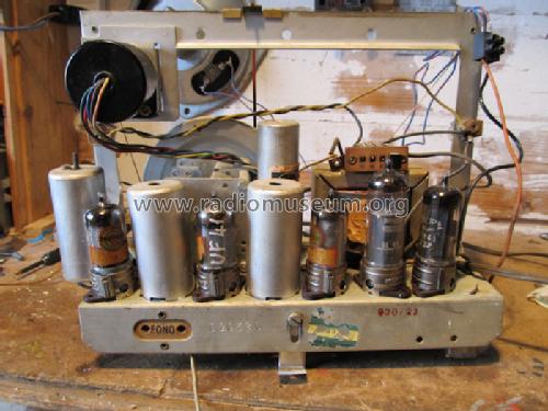
- Anzahl Röhren
- 6
- Hauptprinzip
- Superhet allgemein
- Wellenbereiche
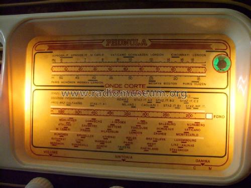
- Mittelwelle und Kurzwelle.
- Betriebsart / Volt
- Wechselstromspeisung / 125-220 Volt
- Lautsprecher
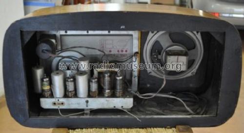
- Dynamischer LS, keine Erregerspule (permanentdynamisch)
- Material
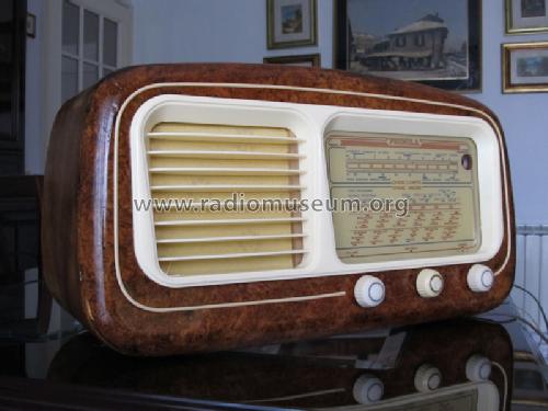
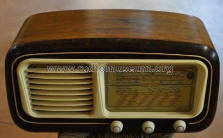
- Gerät mit Holzgehäuse
- von Radiomuseum.org
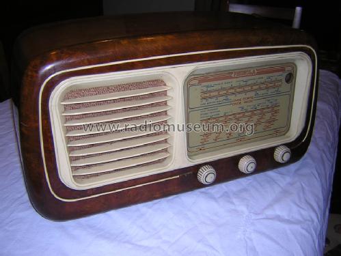
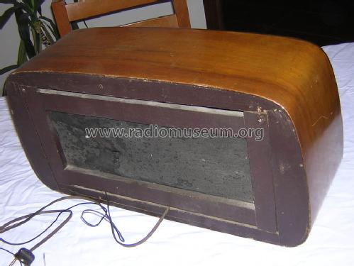
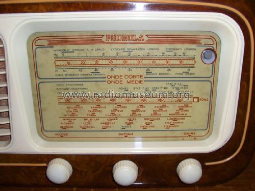
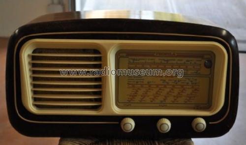
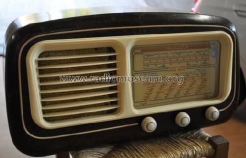
- Modell: 5567 - Phonola SA, FIMI; Saronno VA
- Form
- Tischgerät-gross, - Querformat (breiter als hoch oder quadratisch).
- Abmessungen (BHT)
- 530 x 280 x 220 mm / 20.9 x 11 x 8.7 inch
- Datenherkunft
- Guida Pratica Antique Radio V (2003)
- Autor
- Modellseite von Alessandro De Poi angelegt. Siehe bei "Änderungsvorschlag" für weitere Mitarbeit.
- Weitere Modelle
-
Hier finden Sie 717 Modelle, davon 464 mit Bildern und 545 mit Schaltbildern.
Alle gelisteten Radios usw. von Phonola SA, FIMI; Saronno (VA)
Sammlungen
Das Modell befindet sich in den Sammlungen folgender Mitglieder.
Forumsbeiträge zum Modell: Phonola SA, FIMI;: 5567
Threads: 1 | Posts: 3
I moved this topic, started speaking of the Phonola 5512, as new thread to the right model.
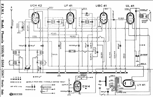
Well, in order to examine the power supply section, we find two diagrams for this model. Even if the layout of components is different, the circuits are quite the same. I say ‘quite the same’ because of the different EM4 pin names on the two diagrams.
 |
 |
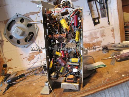
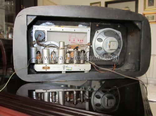
First of all, we note unusual hybrid solutions. Heaters are connected to taps of primary windings on the power supply transformer, used as an auto-transformer. A separate winding is used, with a half-wave rectifier, to generate the anode supply voltage. The use of an auto-transformer was crazy from a safety point of view, nevertheless quite common in those years, to save on the size and cost of the iron core. Anyway we see that only about one half of the total power, that related to heaters, is handled by the primary side. The remaining power, from the secondary winding, goes to the half-wave rectifier. This circuit, producing unidirectional current flow and then a magnetization of the iron core, requires larger sections of the core itself. And anyway it asks for considerably larger and by far more expensive filter capacitors. We find a 50 + 50 uF, quite rare in those years. Saving on the transformer copper was more or less nullified by the amount of workmanship, required to wind the various sections of the primary, each with different wire size.
Anyway, giving a hasty look at the diagrams, we could have the impression that the designer wanted to offer a brilliant solution to the problem of the galvanic insulation of the chassis. Actually the metal chassis looks fully floating and insulated from the ac mains. But this appearance is deceptive at all: this radio, as most of the Italian sets, can be very harmful for its users.
To follow the possible conduction paths, we can simplify the circuit as follows.
H1 and H2 are the heater pins and K is the cathode of the EM4, regardless of the pin numbering on each diagram. Now we can easily see that the thin alumina insulating layer, between heater and cathode of EM4, in parallel to the 10 nF capacitor, is the barrier that separates one of the AC mains wire from the chassis. This layer is specified to withstand 100V max AC or DC voltage.
Therefore, if users touch the braid of the shielded cable to the record player arm, the same body of the phono pick-up, or even an unprotected metal shaft, maybe due to a missing or broken knob, they are protected by a layer capable of just withstanding about 100 volts. Certainly the designer did not read the EM4 datasheet or missed this parameter at all. I could bet that he specified 630V or more as voltage rating for the 10 nF capacitor in parallel. So we look at an incomprehensible mixture of poor and even stupid circuit solutions to electrocute customers.
Blame on this design!
Emilio Ciardiello, 30.Apr.12