pilot: H-664 Push Button Mechanism in Pictures
pilot: H-664 Push Button Mechanism in Pictures

Dear Colleagues,
I eventually resolved the Pilot H664 tuning mehanism by doing what I dreaded most - entirely dismantling it. Some questions still remain, but here I will briefly attempt to explain how it works.
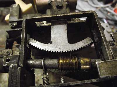
The basic mechanism is a worm drive attached to a spindle through a quadrant gear as shown below:
 |
| Worm Gear - The spindle is clearly visible. |
The next photo is a close up of the worm drive:
 |
| A Better view of the quadrant gear |
Under normal tuning, the worm gear is engaged with the quadrant gear. When automatic tuning is in operation, the gear is disengaged, as shown above. A linkage disengages the worm gear when automatic tuning is used. To return to normal tuning, the tuning knob is pushed down and clicks into place engaging the worm drive and quadrant. I haven't shown the linkage.
The next photo shows the anti-backlash gears attached to the tuning capacitor.
.jpg) |
| Anti-backlash gears. The tuning spindle is attached to the arm with the two springs |
The tuning spindle is attached to the arm with the two springs-the cranks turn the tuning capacitor via a step-up gear and also the drum.
Automatic tuning is accomplished by having rack and pinion gears turn the spindle. The station is tuned and then the gear for the preset station is locked to the spindle by a clamping action. The clamping is done by two wedges that force the pinion gears against the ends of the spindle.
 |
| Turning the shaft forces the two projections from the wedges (See next photo) together. |
 |
| Dismantled gearbox showing rack and pinion. The clamping wedges are in the centre, and the ends of the spindle can be seen projecting from the gearbox. The pinion gears can rotate on the spindle until they are clamped by the wedges forcing them against the spindle ends |
The automatic tuning is done by the keys pressing on the ends of the racks, as shown in the following diagram:
 |
| In this diagram, the spindle is clamped to the pinion. Pressing the button acts on the racks to turn the spindle clockwise or anti-clockwise. When the ends of the racks are level, the station is in tune. |
There are some questions, though. In normal operation, the tuning knob engages the quadrant gear through a worm drive. This would seem to be inherently full of backlash and indeed tuning this set was quite uncomfortable. This seems an odd aspect of the design.
The second problem is not well understood. The spindle was too large for the gearbox, and simply would not turn. This was resolved by reassembling the gearbox with shims under the screws that held the lid together. I considered removing a thou by turning the spindle in a lathe - but I really hate doing that sort of thing. How could this mis-fit have happened.
Hope this wll be of interest to a few - Bryce
To thank the Author because you find the post helpful or well done.
pilot: H-664 Push Button Mechanism in Pictures

Hi
I have just dismantled the push bitton mechanism in my Pilot HS-485 and it is identical to your description.
Your description is invaluable to what I am trying to do allow me to come back with questions eventually!
Thanks and Regards
To thank the Author because you find the post helpful or well done.
pilot: H-664 Push Button Mechanism in Pictures
Hello
I had to dismantle the same mechnaism in my pilot 485. The whole thing is a mess with huge backlash that is nearly impossible to eliminate
At the end of the day I simply disabled the buttons but the backlash is still there, what can you do...
To thank the Author because you find the post helpful or well done.