- Pays
- Etats-Unis
- Fabricant / Marque
- Pilot Electric Mfg. Co. (Radio Corp.); Brooklyn (NY)
- Année
- 1938
- Catégorie
- Radio - ou tuner d'après la guerre 1939-45
- Radiomuseum.org ID
- 18878
-
- alternative name: Pilot Radio & Television || Pilot Radio and Tube || Pilot Radio Corporation


Cliquez sur la vignette du schéma pour le demander en tant que document gratuit.
- No. de tubes
- 6
- Principe général
- Super hétérodyne (en général); FI/IF 455 kHz
- Circuits accordés
- 6 Circuits MA (AM)
- Gammes d'ondes
- PO et 2 x OC
- Tension / type courant
- Alimentation Courant Alternatif (CA)
- Haut-parleur
- HP dynamique à électro-aimant (électrodynamique)
- Puissance de sortie
- 4.8 W (qualité inconnue)
- De Radiomuseum.org
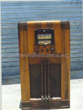
- Modèle: H-664 - Pilot Electric Mfg. Co. Radio
- Remarques
- Tuning eye; different power transformers for 110-125 V, 150 V, 220-240 V and 110-125 / 220-240 V.
- Source extérieure
- E. Erb 3-907007-36-0
- Source du schéma
- Die «Thali Schemasammlung» führt das Modell.
- Schémathèque (1)
- Rider's Perpetual, Volume 9 = 1938 and before
- D'autres Modèles
-
Vous pourrez trouver sous ce lien 544 modèles d'appareils, 273 avec des images et 412 avec des schémas.
Tous les appareils de Pilot Electric Mfg. Co. (Radio Corp.); Brooklyn (NY)
Contributions du forum pour ce modèle: Pilot Electric Mfg.: H-664
Discussions: 2 | Publications: 10
Dear Colleagues,
I eventually resolved the Pilot H664 tuning mehanism by doing what I dreaded most - entirely dismantling it. Some questions still remain, but here I will briefly attempt to explain how it works.
The basic mechanism is a worm drive attached to a spindle through a quadrant gear as shown below:
 |
| Worm Gear - The spindle is clearly visible. |
The next photo is a close up of the worm drive:
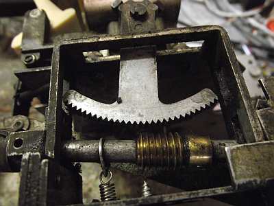 |
| A Better view of the quadrant gear |
Under normal tuning, the worm gear is engaged with the quadrant gear. When automatic tuning is in operation, the gear is disengaged, as shown above. A linkage disengages the worm gear when automatic tuning is used. To return to normal tuning, the tuning knob is pushed down and clicks into place engaging the worm drive and quadrant. I haven't shown the linkage.
The next photo shows the anti-backlash gears attached to the tuning capacitor.
.jpg) |
| Anti-backlash gears. The tuning spindle is attached to the arm with the two springs |
The tuning spindle is attached to the arm with the two springs-the cranks turn the tuning capacitor via a step-up gear and also the drum.
Automatic tuning is accomplished by having rack and pinion gears turn the spindle. The station is tuned and then the gear for the preset station is locked to the spindle by a clamping action. The clamping is done by two wedges that force the pinion gears against the ends of the spindle.
 |
| Turning the shaft forces the two projections from the wedges (See next photo) together. |
 |
| Dismantled gearbox showing rack and pinion. The clamping wedges are in the centre, and the ends of the spindle can be seen projecting from the gearbox. The pinion gears can rotate on the spindle until they are clamped by the wedges forcing them against the spindle ends |
The automatic tuning is done by the keys pressing on the ends of the racks, as shown in the following diagram:
 |
| In this diagram, the spindle is clamped to the pinion. Pressing the button acts on the racks to turn the spindle clockwise or anti-clockwise. When the ends of the racks are level, the station is in tune. |
There are some questions, though. In normal operation, the tuning knob engages the quadrant gear through a worm drive. This would seem to be inherently full of backlash and indeed tuning this set was quite uncomfortable. This seems an odd aspect of the design.
The second problem is not well understood. The spindle was too large for the gearbox, and simply would not turn. This was resolved by reassembling the gearbox with shims under the screws that held the lid together. I considered removing a thou by turning the spindle in a lathe - but I really hate doing that sort of thing. How could this mis-fit have happened.
Hope this wll be of interest to a few - Bryce
Bryce Ringwood, 15.Jul.12
Dear Colleagues,
I have encountered a very gummed-up Pilot H664 with push-buttons that seem to do nothing. The tuning knob rocks up and down to engage a worm-drive, but it also slides in and out - which doesn't seem correct.
I am at this stage somewhat fearful of taking the entire mechanical drive apart.
Can anyone tell me how the tuning is meant to operate ?
Regards - Bryce
PS - I have visions of stripped rack and pinion gears.
Bryce Ringwood, 11.May.12