Relaxation Oscillations In LC-Oscillators
Relaxation Oscillations In LC-Oscillators

Relaxation oscillations are a frequently encountered phenomenon in nature. In electrical engineering, relaxation oscillators like the astable multivibrator have numerous applications. The figure below shows a typical relaxation oscillation in an electronic system producing an output voltage U(t).

The typical pattern of relaxation oscillations is a relatively slow decay of the output starting from the positive extremum, followed by a sudden jump to the negative extremum, followed again by a relatively slow decay and another sudden jump to the positive extremum again at which the cycle then repeats. Obviously, relaxation oscillations are fundamentally different from sinusoidal harmonic oscillations.
Our interest is therefore naturally directed towards systems that are capable of exhibiting both, (approximate) harmonic oscillations and relaxation oscillations. It may come as a surprise that an LC-oscillator is such a system since this type of oscillator is usually associated with harmonic oscillations. We shall therefore investigate the occurrence of relaxation oscillations in LC-oscillators in the paper presented here.
For further reference and keywords the abstract of the paper is given below:
The occurrence of relaxation oscillations in LC-oscillators is studied from a theoretical and experimental point of view with appropriate attention given to the transition between harmonic oscillations and relaxation oscillations. A generic model circuit for a tuned input, inductive feedback LC-oscillator is introduced and a Liénard type differential equation governing it's behavior is derived. After acquiring a basic understanding of relaxation oscillations by studying Van der Pol's differential equation, a diode clipper is introduced into the LC-oscillator tank and it is shown that the resulting oscillator is qualitatively similar to the Van der Pol oscillator. The resulting differential equation is then solved numerically and it is shown that this oscillator can, as expected, exhibit harmonic oscillations as well as relaxation oscillations. Finally, a practical circuit of an LC-oscillator with LC tank diode clipping that can show harmonic oscillations as well as relaxation oscillations is presented.
Attachments:
To thank the Author because you find the post helpful or well done.
Relaxation Oscillations In Emitter Coupled LC Oscillators
The emitter coupled LC oscillator is a two terminal oscillator that does not require a tickler coil (Armstrong/Meissner) or a tap on the LC tank coil (Hartley) or capacitor (Colpitts). Instead the entire LC tank is connected across the two terminals of the amplifier/feedback device. The emitter coupled LC oscillator is therefore often used in LC tank test circuits where the LC tank under test must not be modified. The basic version of the emitter coupled LC oscillator is shown in the diagram below:

The adjustable current sink at the common emitter connection that is used for feedback control is often simply replaced by an adjustable resistor.
Let us therefore take a closer look at this circuit. (The reader not interested in the details may at this point skip to the conclusions after the presentation of the differential equations.) From the circuit diagram, it follows that the emitter coupled LC oscillator can be modeled by a transconductance feedback device with input and output connected directly as shown in the following diagram:

As in the previous paper, we have modeled the losses in the LC tank by a parallel loss resistance RP. Input and feedback current shall again be given by
By virtue of Kirchhoff's circuit laws we obtain
Differentiating the left of the above equations with respect to time gives
We can now use
along with
in the above expression and obtain
Obviously, this differential equation governing the behavior of the circuit is very similar to the differential equation
for the generic inductive feedback circuit that was derived in the previous paper (equation #5). In fact, for an inductive coupling factor of k=1 and a feedback coil Lf that has the same inductance as the tank's coil L, the two equations converge.
Indeed, a closer look at the circuit shown at the very beginning of this post reveals two diodes in opposite directions across the LC tank: The base-collector diodes of the two transistors T1 and T2!
Since the circuit in it's basic form is operated with a DC bias voltage of base and collector of both
transistors that is the positive supply rail voltage, severe diode clipping and pronounced relaxation
oscillations with a frequency much lower than the resonant frequency of the LC tank will already set
in at oscillation amplitudes approaching 0.6Vp.
As the transition from nearly harmonic to relaxation oscillations is gradual, even before pronounced
relaxation oscillations occur, the frequency of the oscillations will start to drop significantly at
oscillation amplitudes even well below 0.6Vp.
Now that we have understood the problem of the emitter coupled LC oscillator in it's basic form, let's
find a way to raise the permissible amplitude of the oscillations. This can simply be done by placing
an array of n silicon diodes in forward direction before the base of each transistor, raising the threshold for an appreciable base-collector current. These diode arrays will however have no effect on the general feedback function of the circuit. This can be seen from the fact that now the emitter voltage will follow the base voltage at a distance of (n+1)*0.6V while without the diode array it was 0.6V. However, since
still holds true in this case, the small signal AC behavior of the circuit is not altered and feedback continues to be provided as before.
The diagram below shows such an improved emitter coupled LC oscillator used for LC tank testing.
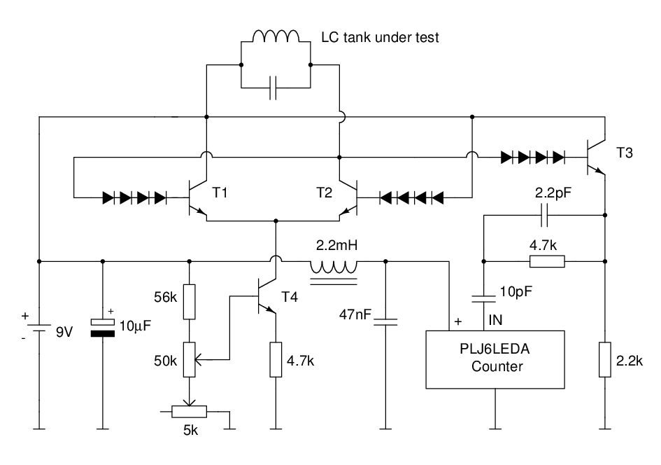
The feedback level in this circuit is controlled by setting the common emitter current by adjusting
the 50kΩ (coarse) and 5kΩ (fine) potentiometers in the emitter current sink (T4). An emitter follower (T3) is used to drive a frequency counter module, allowing for stand-alone operations without an oscilloscope or frequency counter.
To thank the Author because you find the post helpful or well done.
Parasitic Capacitances vs. Relaxation Oscillations
What we have obtained so far is a theory that predicts a pronounced drop in the output frequency of the emitter coupled oscillator as the feedback level is increased and the transition from harmonic to relaxation oscillations begins. This frequency drop has been observed in previous applications of the emitter coupled oscillator. There, however, it was suspected that the frequency drop is caused by a change of parasitic capacitances of the transistors as the quiescent voltages and currents are altered.
Let us therefore perform some measurements in the emitter coupled oscillator circuit as shown near the end of post #2 and see if we can find experimental evidence to support our theory that the oscillation frequency drop is primarily caused by the transition from harmonic to relaxation oscillations. If this is the case, there should be a strong correlation between the drop in the oscillation frequency and the onset of amplitude clipping in the LC tank as the feedback level is increased. Since the feedback level in the above circuit is determined by the common emitter current set by the current sink, we shall measure oscillation frequency and amplitude for increasing values of the common emitter current.
For this experimental setup, we have deliberately used BC547C transistors and 1N4001 diodes having
much greater parasitic capacitances than designated high-frequency transistors and diodes. The reason for this is simple: If varying parasitic capacitances play a significant role in the frequency drop behavior, we want this to show up as prominently as possible.
We'll start with the original emitter coupled oscillator. This setup can easily be created from the circuit above by short-circuiting the diode arrays, and the results are shown in the diagram below.

As expected, we see a strong correlation between the frequency drop and the onset of amplitude
clipping through the base-collector diodes of the transistors. In fact, before the onset of amplitude
clipping at a common emitter DC current of roughly 4μA, there's very little change in the oscillation
frequency. This strongly supports our theory that the pronounced drop in oscillation frequency is due to the onset of relaxation oscillations and not caused by transistor capacitances varying with the quiescent DC voltages and currents in the circuit.
Now, let's remove the short circuit wires and put the diode arrays into effect again. What we expect is amplitude clipping and frequency drop to be strongly correlated again, but this time to set in at a
considerably higher amplitude respectively feedback level. Indeed, this is what we observe:

Again, there's very little change in the oscillation frequency before the onset of amplitude clipping at around a common emitter current of roughly 35μA.
In summary, the parasitic capacitances of the transistors (and diodes in the improved emitter coupled
oscillator setup) seem to decrease the oscillation frequency of the circuit by a roughly constant factor. The pronounced frequency drop, however, occurs due to the transition from harmonic to relaxation
oscillations.
To thank the Author because you find the post helpful or well done.
 Thread closed by a moderator. But replies can be made through a moderator.