crosley: Restoration Crosly 52
crosley: Restoration Crosly 52

As I wrote in my previous article, when I found this radio at the flea-market, it was in very bad condition, with a lot of missing parts. Despite of that, I have purchased it for several reasons: it's very strange to find such an American vintage model here in Eastern Europe. Also, it seems to be a rare model, even at the RM only one member posted that model. Finally, its restoration would be a real challenge for me.
The first pisture shows the radio as it came.

Both knobs are missing as well as the volume control plate.
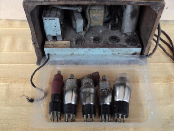
Next picture is a back appearance and the tubes I found inside. Back cover is missing, one tube was not original and two other were dead.
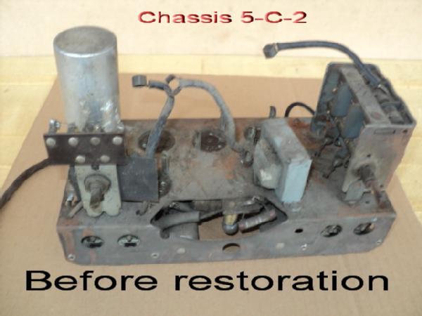
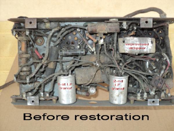
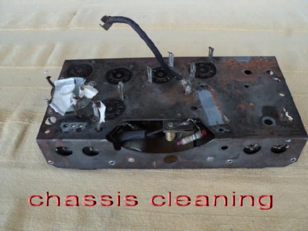
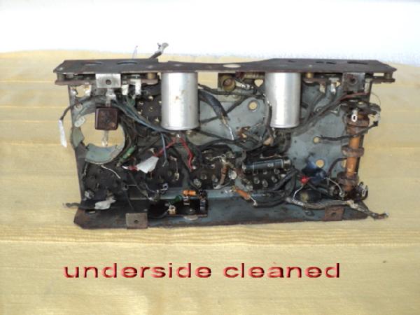
Next two pictures show both sides of chassis:
„Speaker horror“
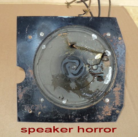
Restoration and reconing the speaker was described in my previous article, but here I only want to remind you how it looked like!
Restoraton begins with cleaning. The chassis was cleaned using metal brush and anticorrosion fluid.
To clean the tube socket contacts I used an interdental brush and contact-cleaning fluid.

By sockets for first two tubes you can see fixation springs for tube shields, which also were missing. After some search I happily have found, at the eBay, the original type shields. There I also have found replacements for missing and burned-out tubes.
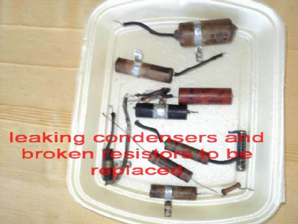
After cleanig the chassis, I had to check all parts. Some capacitors were leaking and resistors were broken or open, including the dropper, which was improvised sometimes in the past.
Next photo shows all parts to be replaced:
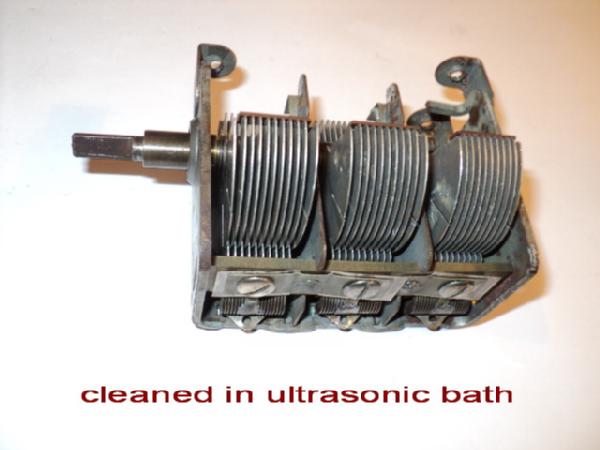
Variable capacitor was cleaned in ultrasonic bath.
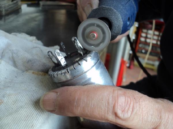
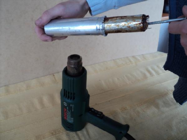
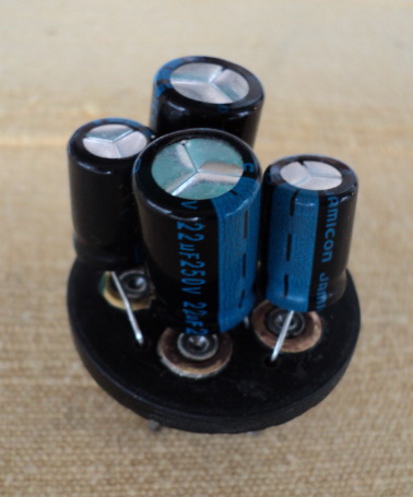
As I do always, all paper smoothing and blocking capacitors had to be replaced with good electrolytics. To restuff its can, I had to open it, pull out the old capacitors and raplace them with modern electrolytics. All steps of doing that are shown in following pictures:

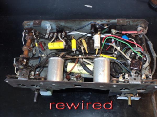
Now, the chassis is rewired with new parts and some connecting wires with crumbled isolation were changed.
And now came time for some cosmetics. First, the cabinet. It was so damaged that I had to give it to an proffesional furniture restorater. Here si how it looks after his work:

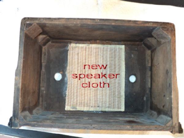
New speaker cloth is not even close to original, but when I find something better, it could be replaced.
Since the rectifier and output tubes generate much heat which can damage the cabinet finish, I put some protecton:

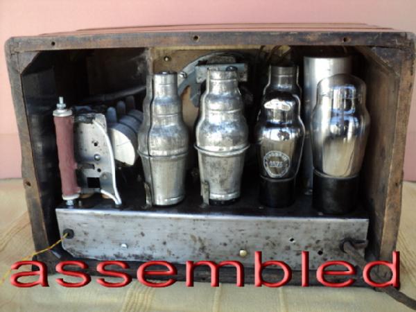
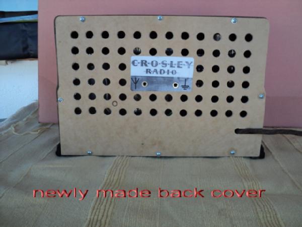
Now the radio was assembled and an new back cover was made.
There were some problems at the front. When came, radio had only one front plate (tuning control). Second one, for volume control, was missing. Copying the size and shape of existing plate, I drew the plate for volume control and gave it to professional engraver to make it of nickel-plated brass, 0,5 mm thick. Here they are: at right is the old, original plate and left is the new one, for volume control:
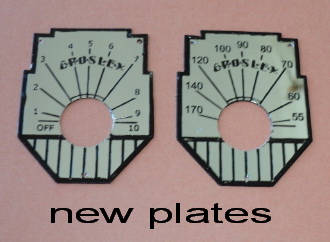
If someone wants to make those plates, I can send the templates by mail.
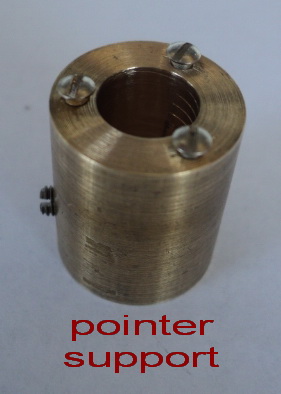
Second problem was the tuning pointer which was missing too. Variable condenser has coaxial 3:1 reduction so that the knob has to be rotate 6 times to get the rotation of 180 degrees of the rotor. Very nice, but I had to make an adapter to fix the pointer at the outher shaft of the condenser. Inner shaft is for the knob. I made that adapter of brass using my lath. The pointer itself was made of transparent plastic with centered red line, fixed at the support (adapter) with three M2 screws.
The original knobs were also missing, so I put what I had, hoping that one day some close to original will be found.
Finally, restored Crosley looks like this:

For alignment I performed standard procedure, using modulated signal of 182 kHz for IF, and oscilloscope. Fortunatelly, the coils were OK and only the IF and trimmer capacirors had to be adjusted.
To ilustrate how it works, I posted an audio clip to its model page. That is BCB-scan, with some interferences from local switching chargers in the neighbourhood. No MW AM stations are active in my country, as in most of Europe, so that only some Hungarian and Romanian stations could be heared with this receiver.
I hope that this presentation can help , and for any details feel free to ask me.
Best regards and enjoy our hobby!
Appended by Dietmar Rudolph
Dejan Momirow wrote on April 1th:
I noticed an error in my last article about the restoration of this radio! In part about variable condenser which has coaxial reduction 3:1 I wrote that you have to turn the knob 6 times to get the full scale rotation (180 deg) of its rotor. But, that is wrong! It should be a half of the reduction ratio, be 1,5 times!
Sorry!
To thank the Author because you find the post helpful or well done.