RF triggered NE-2 neon bulb
RF triggered NE-2 neon bulb

Fellow Radiophiles:
In a recent email exchange, Philbrick alumnus Dan Sheingold pointed out that the precision capacitors in early vacuum tube integrators of the 1950's were sometimes reset to 0V with a neon bulb that was made conductive with an external capacitively coupled burst of RF voltage.
Integrators served as computational blocks in analog computers and accumulated charge on a precision capacitor with swings up to +/-100V. It was necessary to hold all integrator capacitors discharged until the start of an analog computation. This was sometimes done with relays, but the RF triggered neon bulb could assure a more simultaneous start for an analog computation.
Having had a long hobby interest in all gas tubes, I was very surprised to hear that when a gas bulb is driven with capacitively coupled RF voltage to the bulb exterior, DC conduction can be obtained at it's two electrodes even with nearly zero volts, as is the case with a resistor.
Without the RF trigger, there is no conduction at all near zero volts and very little current will leak until the DC trigger voltage at the two electrodes exceeds the characteristic trigger point, which is around 70V for a NE2 neon bulb as shown in the curve tracing on the left.
As a first check of DC conductance across the NE2 neon bulb, I used a conventional analog Ohmmeter to measure DC resistance while I touched the NE2 to one of my decorative plasma globes. This is the kind of clear glass globe with plasma streamers glowing inside that follow your finger if you touch the glass. These globes operate with RF at a few 10's of kHz and a few thousand volts, but a very low safe current that hardly produces a tingle. It is this leaked RF energy at the surface of the globe that makes the NE2 bulb glow. My casual measurement showed values of resistance between 10k and 100k. My Ohmmeter uses a 1.5V cell to create a test current for resistance measurements, so no more than 1.5V DC was applied to the NE2. In the voltage scale of my meter I measured up to 0.5VDC with the 100k load of the meter when I angled the bulb to make one of the two rods glow more than the other. If you have a plasma globe at home, you can try these measurements. Alternatively, you can use a Teslator, as demonstrated by Prof. Rudolph, to turn on the neon bulb with RF energy. I have found that a small 3" plasma globe display can be used with the globe non-destructively removed as a Teslator.
These results just stimulated more curiosity, so I decided to "throw" the NE2 on the curve tracer, as Jim Williams used to say.
The following circuit applies 500Vp-p at 1MHz to a piece of 0.1"(2.5mm) copper tape wrapped around the neon bulb. I used a conventional Ferrite AM loopstick antenna to step up the 10Vp-p from the generator up to 500Vp-p at the external bulb tape wrapper. The output capacitor must be tuned for maximum output.
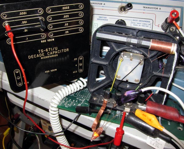
The NE2 with the copper tape wrapped around it, glows near the bottom of the photo.
The 1000pF capacitor keeps RF out of the measurement NE2 electrodes and helps even out the glow over the two rods with the AC short across the two terminals.
Note the primary winding at the far right of the ferrite rod. There is some leakage inductance between the two windings. This and the very high secondary Q of several hundred at 1MHz, explain why the step-up ratio is higher than the square root of the ratio of the winding inductances at resonance.


Note that the DC resistance around 0VDC is about 2k, and increases beyond 10k with a few DC volts.
These plots make it clear that neon bulbs could be used to discharge capacitors to 0VDC with pre-discharge voltages up to 50V. Neon bulbs with a higher DC trigger voltage could have been used to discharge up to 100V on a capacitor. Current limiting resistors might be a wise practice to prevent damage with the initial discharge of larger voltages. The offset voltage is also a few 10's of mV, but less offset might be obtained with greater care to apply the RF energy more evenly to both electrodes.
Another interesting aspect of RF triggering is that it applies the same triggering potential to the plasma as might be applied at DC via the two electrodes. I confirmed with a 100V pulse generator up to 2MHz, that the trigger voltage of 70V is the same at DC as at 2MHz when applied directly to the electrodes.
But once the plasma is triggered by the RF energy, very little DC or AC develops across the electrodes. Remember that neon bulbs can't oscillate any faster than a few 10's of kHz, so the plasma should change little in response to 1MHz RF stimulus.
An alternate method to excite the neon bulb with RF night be to have two external electrodes to apply the RF capacitively, so that the internal electrodes don't have to be used for the return path of the RF circuit. This might provide for lower offset voltages too.
Best regards,
-Joe
To thank the Author because you find the post helpful or well done.
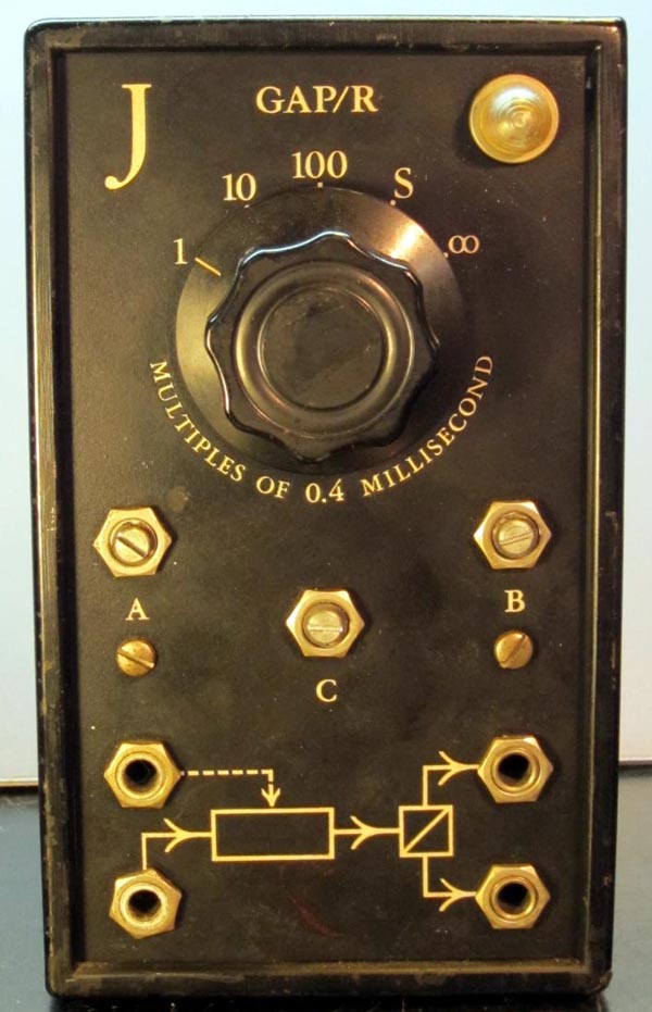
Philbrick K3-J integrator is reset by RF controlled NE2
Fellow Radiophiles:
Dan Sheingold pointed out that the "K3-J Integrating Component" made by GAP/R (George A Philbrick / Researches) as an Analog Computer building block, used the NE-2 neon bulb to reset the integrator to 0V with the application of RF energy to the exterior of a NE-2 bulb.

The following schematic shows the NE-2 bulb under RF control of the gated oscillator made with the small 6AK5 RF pentode. A positive voltage at the CLAMP input enables the RF oscillator, which applies sufficient RF voltage to the exterior of the NE-2 neon bulb to turn on the bulb and reset the integrating capacitors at the selector switch through the auxiliary K2-W feedback amplifer "I". A negative voltage at the CLAMP input shuts off the 6AK5 and the RF oscillations and the integrator is allowed to integrate the input voltage at the IN jack.
The strangely numbered "8386118" component is a Thyrite, which is a bidirectional clamping element. When the voltage across it is less than it's limit value, it behaves as a high impedance. This means that during integrator reset the auxiliary opamp "I" operates at high gain to make any DC errors induced by the NE-2 negligible during integrator reset. This technique was later used in early monolythic Sample and Hold amlifiers that were built with bipolar processes.
As a result of a very lucky purchase that was suggested by Philbrick enthusiast Achim Dassow, I bought a several of the K3 units a year ago, and a "K3-J Integrating Component" was part of the lot.

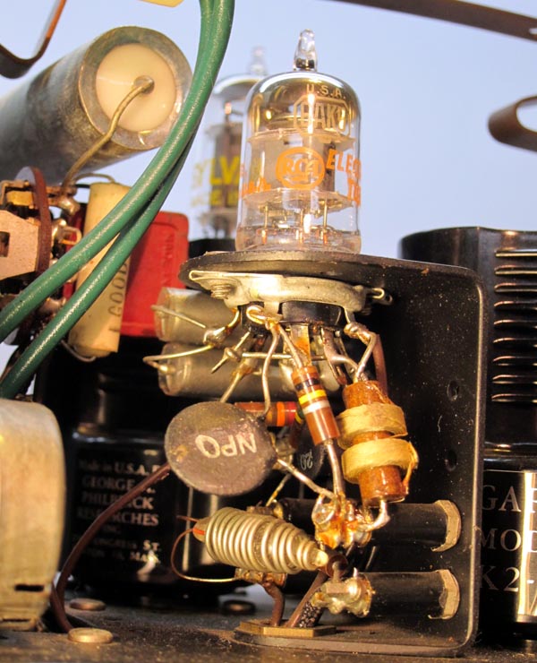
Note the NE-2 bulb under the 6AK5 gated oscillator, completely wrapped with solid wire for the application of the RF control voltage.
More info relating to other analog computing elements from GAP/R can be found at the Philbrick Archive.
Regards,
-Joe
To thank the Author because you find the post helpful or well done.
Thyrites
Fellow Radiophiles:

The Thyristor component in the auxiliary feedback amplifier "I" in the K3-J is a bidirectional diode with a power law characteristic with the exponent between 2.49 and 3.36. This Thyrite characteristic was used in the 1950's to build analog multipliers. See Thyrite in analog multiplier.
"Thyrite" is a registered trademark of General Electric.
The white arrow marks the location of the Thyristor inside the K3-J shown in this photo.
I curve traced the 8386118 Thyristor that was wired across the feedback of the auxiliary feedback amplifier.


The 27k input resistor of amplifier "I" will combine the Thyristor impedance for a non inverting gain of 2 when the voltage across the Thyristor is about 100V. The amplifier is effectively clamped at this point. If the voltage is less than 30V, the impedance is in the Megohm range and the gain of amplifier "I" becomes very high, approaching open loop gain conditions (Avol for the K2-W is nominally 15000). It is this very high gain that hides any voltage drop errors across the NE-2 reset switch.
Regards,
-Joe
To thank the Author because you find the post helpful or well done.