saba: SABA UA-345 (UA345);
saba: SABA UA-345 (UA345);

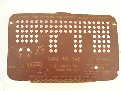
I had recently upload a new model SABA UA-345. It is in my collection.
http://www.radiomuseum.org/dsp_modell.cfm?model_id=75660

I don't know much about it. I've not its schematic and I don't know its IF value. May be 452kc/s? It has only two IFTs, but it has a lot of RF adjustment screws. I'm not sure they are rightly tuned. It works but it can´t receive any broadcasting station.
Do you have any information about it?
It also has one resistor in series in its mains dropper circuit. It has a very high value 10KOhms. That seems to be a thermistor. Do you think possible it is an original component in the years of 40/50 or it is a "recent inovation"?
Best Regards
Mário
EE: I have put an empty line between the two pictures. Now the frame should not anymore "explode".
To thank the Author because you find the post helpful or well done.
What a type is this?

Hallo Mario, let as make a new Job.
General to your set.
This model (UA345) is one of the type: "Export model"
Designed to exporting to countries Worldwide, but not USA, Canada and Scandinavia.
These universal Types for AC and DC (GW) models i mean, is much more specified for customers with DC, or sometime AC, then the power consumption of this versions are higher as the AC (W) models. The whole German industries make such export sets.
It is very difficult to becomes a information for this Types. Our Friend and Member, Robert Sarbell , have the same Problems (Blaupunkt, Nordmende)
Why? It was not usual to serve such sets in Germany. This is the reason why we cannot find something. Only an employee of SABA can have this one. I have never heard some name or address from anybody.
On other hand, some servicemen in that countries, that sales this Radios, is the only address for that.
I have maybe, the most SABA Service -Information's for Germany. But not one for export.
I give my suggestion:
Look here: SABA Triberg GW52 http://www.radiomuseum.org/dsp_modell.cfm?model_id=20017
I think this is the nearest Design to your Sample. Only Wave Ranges (L,M,K) is changed in K,K,M. Only UK use Long Wave in the Export Market. Also the Tubes UBC41 and UL41 is combine to an UCL81. This Tube is not on market, previous to 1951
On RM.org you can see on Pos2 the alignment plan. I have seen, the IF Frequency is 472 Khz. All SABA sets in 1951 to 1953 use this value. I think also yours.
It also has one resistor in series in its mains dropper circuit. It has a very high value 10KOhms. That seems to be a thermistor. Do you think possible it is an original component in the years of 40/50 or it is a "recent inovation
Yes, this is a thermistor.
In Old Germany : URDOX
See here:
Picture 1
The type : U2410 says, if worm, 24 Volt trop on 0,1 Amp. and cold if new, aprox 2000 to 2500 Ohms After 50 Year, much more.
The worm uptime if new: 100 sec.
This component is necessary, to avoid burnout of Pilot-lamp 18V/0,1A when Set goes "on" Without this, lamp is immediately dead! The low resistance of the cold tube -heater destroy that Lamp.
That' s first,
Awaiting your comment.
Hans M. Knoll
To thank the Author because you find the post helpful or well done.
Generate 472kHz
Hallo Herr Hans Knoll
I think your reply couldn't be more substantial and complete than it was.
Thank you very much for your reply and your time (patience), once more. (:-.
It is good to know that:
-IFT's frequency is 472 kHz
-It is a thermistor (URDOX) and it is original.
I've look now at SABA Triberg GW52 schematic, as you said.
Now, I think the next step is to generate 472 kHz on UAF42 grid and on UCL81 grid, to check the two IFT's. Do you agree?
I'll do it next Monday because I've to leave Lisbon this week-end to carry home my oscillator.
I hope you don't mind I send you my next report only next Monday.
Meanwhile I send you a photograph of those two IFT's (1) :
(1) IFT's
and a curiosity:
(2) UCL81 is inside of one B8A socket band, though its base is a correct B9A socket. Strange . Isn't it?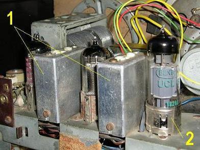
Best regards
Mário
To thank the Author because you find the post helpful or well done.
What at next?
thanks for your comment.
Til monday i give you more and additional informations.
Have a nice weekend.
Hans
To thank the Author because you find the post helpful or well done.
Here is more information about aligment
Hello Mario,
after receive your picture from the IFT, (thanks) I see that the appearance is a new designed type . This was in 1952 to 1953 used in the FM build in Super SABA UKW-SIII. This form is never used on SABA Sets , only in your Export model. That means, I think, the UA-345 is after or in 1952 produced. All other Standard Models, use cylindrical Shields for the IFT's. Later (1956) SABA detach this round form and use new rectangle (AM/FM) IFT's.
here picture1
You:
I think the next step is to generate 472 kHz on UAF42 grid
Yes that right. and on UCH42 not on UCL81 grid, to check the two IFT's.
Do you agree? No, not at all. See alternations above
Right is: Signal injection first on UAF42 and second on UCH42 to test the stages for function.
And: For final alignment please use this modified procedure
(from Sabine 1956) Only the indexes for "L" are wrong
here picture2 
for the moment in "German" Details on request.
This 0.1uF condenser, is connected to the AGC Line
(Regelspannung = AGC Line)
Shielding around the UCL81.
I now this solution. This is a good thing. Some Design use that before the Noval Socket have a shield. The Triode at E/UCL xyz mostly needs this shielding. Particular on PC-boards, to prevent hum and oscillation.
O.K. that's enough for the moment, test it and post your comment
Regards, Hans
Version 1
To thank the Author because you find the post helpful or well done.
IF'Ts tune check
Thank you for your reply.
I had just generate 472 kHz. The response signal is weaker than usual on all points.
It was tested on:
- UAF42 pin 6 OK ------ weak.
- UCH42 better on pin 4 than on pin 6 ------ but weak.
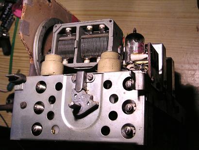
I think it's better not to ajust the trimmers, they are so many (:- (see photo) before a I get a better signal. Do you agree? It will not be a very easy task , I presume.
Meanwile I changed the UCH42 by another one.Then I could ear a very very weak broadcast signal at the botton of the scale.
I had already tested all tubes before I'd started this job. But my tube tester, as some others, can not check all tube parameters.
Well I think I can't go forward before I buy some new tubes. Do you agree?
Best regards
Mário
To thank the Author because you find the post helpful or well done.
IF -Test
i unterstand all!
I will give you answer today evening.
Maybe jou nowing what outgoing Voltage your SG have. When no, is also O.K.
Greadings Hans
To thank the Author because you find the post helpful or well done.
IF test, how to do?
Hello Mario,
Your results about sensitivity are not so good.
Let as find a way to repair this failure.
First: I think that you on a better way, when you test in every situation, to measure all values of voltage around the tubes. I make that all the time and be much happy to due that. Aprox. 70 % failure, is dropout of the correct Voltage on Tubes. I give you here a handmade circuit where you can find those Points. (PDF on attachment)
The circuit around screens (g2) maybe different from TRIBERG. I show two versions. One with interconnected screen between UCH and UAF and one with separate sources. But one is forcible, the UCH must have a bleeder (divider) , UAF not!
After we have find the reason for the low gain, its to test if the Oscillator works. UT and - Ug1 is for this case. To prevent "Osc." stops while measuring , a resistor ( 10 to 200 Kohm) is inline to Voltmeter test tip.
here Picture 1
Testing of IF -gain :
Put an AC Voltmeter that can shows 0,5 Volt AC on Speaker lower side. (5 Ohms)
SG with 30% mod. on IF1, Standard is 1mVolt to 3mVolt If signal for 0,5 V on Spkr.
SG on IF2 on MW Range ( not SW) 1/ 50 to 1/100 = 2 to 1 % from the IF1 value is O.K. ? Gain of UCH is 50 to 100 !
Please dont adjust Trimmers!
So, I hope you have to do. Awaiting jour results.
Hans
PS: way to you not use "Hans"? I have a far friend in Sweden , they say to me: not second name is usual in "S" Government give this order there.
Attachments:- IF- Testing (144 KB)
To thank the Author because you find the post helpful or well done.
A current leakage
Hallo Herr Hans
Thank you for your hand made circuit. It is very clear and pedagogic.
It made clear to me that I did not test right enough the circuits , before.
Your diagnosis was right. Once more! Congratulations Mr. Hans.
I Began by the beginning and suddenly the failure was found in the first capacitor you had indicated in your picture:
pin 5 of the UCH42 --- It is a 100nF - 250V which presents a enormous leakage (100 Ohm).
My excuse:That capacitor had to be desolder to find out the failure...(difficult of acess).
After its replacement:
It sounds now perfectly. Many thanks to You again.
1- Damaged capacitor 2 - UCH42 Pin 5

Best regards
Mário
To thank the Author because you find the post helpful or well done.
Our Final
Hello Mario,
i see, this here: but it can´t receive any broadcasting station.
is not longer your problem.
Please take notice, test always the Voltage around the Tubes.
Mostly you are successful.
O.K. and good luck,
from Hans
To thank the Author because you find the post helpful or well done.
 Thread closed by a moderator. But replies can be made through a moderator.