schaub: Pirol 56GWU measurements and analysis
schaub: Pirol 56GWU measurements and analysis

Fellow Radiophiles:
After a long wait for a lucky auction and with the kind assistance of RM member Mr. Georg Beckmann, who bought and shipped this radio from Germany to me, I got the opportunity to study this fascinating but simple AM-FM two-tube radio. The interesting findings in the operation of this radio also stimulated correspondence between myself and two radio expert RM members Mr. Hans Knoll and Prof. Dietmar Rudolph.
Introduction
Other articles already posted under this Schaub Pirol 56GWU model cover the basic operational details of this radio; I plan to focus on measurements, analysis and observed operational characteristics. The AM part of the radio uses the UEL71 Tetrode/Pentode in a particularly well designed circuit with a single tuned resonant RF tank circuit, where the tetrode serves as regenerative detector and the pentode serves as audio power output tube. The FM part of the radio simply adds a slightly modified superhet front end box with a UCC85 dual triode, that converts the early German 88-100MHz FM band to the 10.7MHz IF, which is then slope-detected by the Tetrode in the UEL71. The audio section, like the rest of this simple radio, is very well thought out, without noticeable distortion and a pleasantly shaped bass boost. One could enjoy listening to the pleasant sound from this radio for hours and forget that it was the simplest AM-FM design in the Schaub product line.
The AM section
The variable transformer coupling for the AM antenna and the separate regeneration control made it easy to obtain very nice sound with adequate selectivity from the AM section.
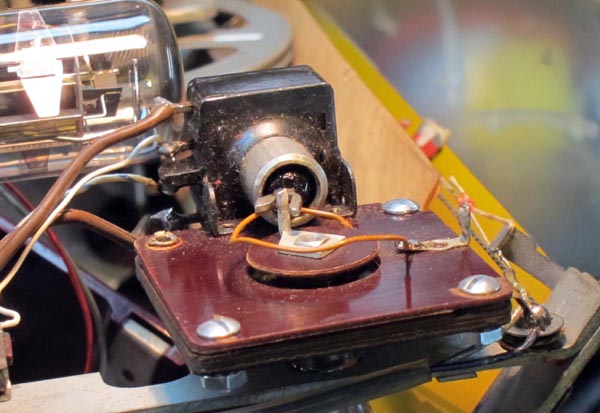 Regeneration - I found the regeneration control exceptionally independent of frequency. In other words, you could set the regeneration control at a relatively high regeneration level, just short of oscillation, and tune the entire AM dial without the appearance of oscillations from excessive regeneration anywhere on the dial. While the oscillation point for the regeneration control on the front of the radio varied less than 5o of rotation throughout the dial, the nearly contemporary Grundig Gloria 51GW has a regeneration control that must be rotated some 30o as new stations are tuned throughout the dial. The control in the picture includes the power switch and the variable capacitor (measured 3pF-180pF) that sets the amount of regenerative positive feedback from the detecting Tetrode plate to the tuned tank circuit. Achieving frequency independence in the regeneration control involves a careful account for the variation in Q of the tank circuit L11-C12 as a function of frequency, which can be minimized by a proper ballance of shunt vs series coil losses. The frequency response of the feedback coil circuit also affects the oscillation point as a function of frequency.
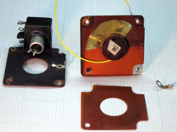 The regeneration control arrived with a partial repair, where 3 of the 4 rivets had been replaced by screws. In the process of completing the repair of the control, I had occasion to take it appart. The original 3pF-180pF range was too wide, where the oscillation point was at less than 1/4 of the shaft rotation. The construction includes 2 thin brass rotor foils sandwiched between 2 aluminun foils separated by phenolic insulators. I moved the middle aliminum stator foil under the end aluminun stator foil to reduce the total capacitance range to 3pF-55pF. The regeneration control now operates with greater ease.
Homodyne detection - After years of playing with several regenerative sets, I have learned to operate them in synchronized additive homodyne detection mode. This a form of synchronous detection where the regeneration control is advanced slightly past the point of oscillation and the tuning is adjusted carefully until the beat whistle disappears and the oscillating frequency of the detector is locked to the incomming station carrier. This radio had a particularly easy and stable lock range, on the order of +/-200Hz at 1030kHz (WBZ 30 miles away in Boston radiation 50kW), judging by the lowest pitch that appears when carrier lock is lost. Very weak signals have a much narrower lock range. Once the local oscillation is locked, the regeneration control can be varied in and out of oscillation without loss of lock. This is a further testament to the frequency independence of the regeneration control.
The Homodyne oscillation amplitude at the detector Tetrode control grid was never more than a few hundred mVp-p. The tetrode always operated without clipping in it's power law transconductance (gm) region. The soft non-linearity of this power law serves to stabilize oscillation amplitude without significantly distorting the much smaller modulation envelope riding over the local oscillation. The advantage of this type of additive homodyne detection over simple regeneration is that the distortion that often accompanies non-oscillating regenerative detection drops dramatically and bandwidth also widens to produce the sensation of High-Fidelity reception. The drop in distortion can be understood from the drop in percent modulation, as the local oscillation greatly boosts the carrier amplitude. With the positive side of the envelope so far from the negative side of the envelope, the grid leak diode looks like a nearly ideal diode where the grid diode is completely off for negative RF peaks and is on with a fixed resistance on the positive peaks. Under homodyne detection, I am hard-pressed to find a better sounding AM radio of the same size in my collection.
But Homodyne detection has it's caveats. First off, some of the energy at the oscillating frequency is radiated back out the AM antenna. When the oscillator is locked, this is perfectly harmless, and actually benefits the reception of radios nearby as the total carrier energy is boosted, which facilitates detection and improves fidelity. When the oscillation looses lock, then whistles are audible in the Pirol as well as in any nearby radio. But this energy is very small and probably will not reach your neighbours (see "A few RF interference measurements").
Additive vs Multiplicative synchronous AM detection - The very clean Homodyne operation of this radio served to clear up a misconception on my part. Ideal synchronous detection differs from the self-oscillating homodyne detection in this radio in one fundamental way. While ideal synchronous detection pushes all neighboring channels into super-sonic frequency beats outside the transmitted 5kHz audio bandwidth, thus greatly benefiting selectivity, no such benefit exists with the Homodyne operation of this radio. In fact, as I advance the regenerative control for stronger local oscillations, the selectivity drops and I can hear strong neighboring stations. The intuitive explanation is that with this kind of Homodyne detection, a relatively low amplitude oscillation is developed that is equivalent to receiving a station with a very strong carrier, but relatively low modulation. This helps envelope detection for the desired station but does nothing to prevent envelope detection for the neighboring stations. This form of homodyne detection can be described as aditive, with the incomming signal and the local oscillation added at the envelope detector, while ideal synchronous detection is multiplicative. Purely multiplicative detection does not let input signals reach the output without being heterodyne first. The reduced selectivity when the regenerative control is advanced further past the oscillation point is due to the fact that bandwidth and selectivity are at their peak at the oscillation point and drop when regeneration is increased or decreased away from this optimum. But it is this softening of selectivity with over-regeneration that makes for nice reproduction of higher audio frequencies under Homodyne detection. Signal gain is also at a peak at the point of oscillation and drops on either side of the oscillation point.
The FM section
 The regenerative slope detection of the IF frequency was the last circuit configuration that was used before the standard FM superhet topology with IF amplifiers stages and FM discriminators was universally adopted for all price ranges. Before this combination of standard FM front end followed by slope detection, the innexpensive FM detection configuration was with super regenerative detectors, which had the disadvantage of radiating interference back to the antenna.
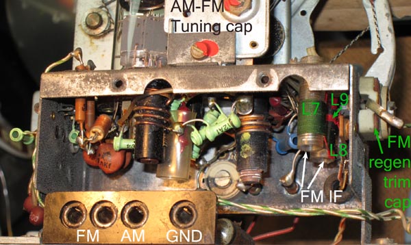
This FM section does not radiate spurious energy at the channel frequency and it also operates with the better selectivity that superhet conversion affords with a single-tuned RF tank and a double tuned standard IF transformer. The original alignment instructions aim to tune the two IF transformer coils L7 and L8 to the same 10.7MHz frequency, as is customarily done with IF transformers. 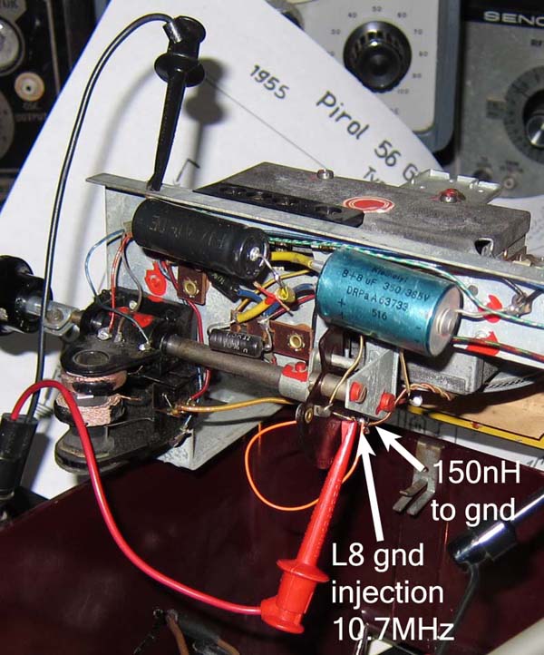 The goal is to produce a peaked response with reasonably linear side slopes for grid-leak detection by the Tetrode in the UEL71. The sharpness of the peak is controlled by the feedback circuit L9-C22 into the secondary IF coil L8 and also by the adjustable R6<200kΩ load. The original alignment sought to control this peak shape with a recommendation that 50uV-100uV at the input with 30%AM modulation on an RF test signal should produce 50mW at the 5Ω speaker. The recommended alignment procedure makes use of the parasitic inductance in the ground leg of L8 to inject the fixed frequency AM-modulated 10.7MHz signal. I measured approximately 150nH to ground at the ground leg of L8. The identical primary and scondary coils measure 12.6uH each with Q=60 and have a measured coupling factor k=0.02 at 200kHz. With this signal injection, a small voltage injection results in greatly magnified voltage at the secondary L8 because of impedance transformation. A full explanation of this signal injection method is found at "Resonanz-Transormation". Injecting the signal this way at the secondary also means that secondary L8 is tuned for peak response, while the primary L7 is tuned for peak absorption, or a minimum response in the speaker output.
Modern 75kHz FM deviation - The FM deviation in the 1950's was usually 40kHz peak, as opposed to the modern 75kHz (deviation figures from private email with Prof. Dietmar Rudolph). This means that the original FM-IF alignment procedure is likely to produce more distortion for weaker signals when the value of R6 is increased for greater sensitivity and the FM-IF response is sharpened, which produces steeper more non-linear detection slopes on either side of the 10.7MHz peak.
 After studying frequency sweeps of the IF transformer with its secondary regeneration, it became clear to me that an alternative alignment could produce a very nice tilted top frequency response with very selective sharp slopes on the sides. Now the carefully tilted detection slope is at the center of the channel and undistorted sound reproduction is obtained for stations that are weak enough to produce hiss. Click on the figure to see a range of sweep shapes and top tilts, that is obtained when the L8 secondary load R6 is varied. The effect of the variation in R6 is roughly equivalent to a variation in the internal FM regeneration control C22. The probe point for these sweep photos was the control grid of the ouput pentode at UEL71 pin3. The sweep response at the pentode plate is distorted by the bass boost filter response, and the slope detector tetrode plate still has 10.7MHz content that would have been disturbed by the ~10pF load of standard 10x 10Meg scope probe. A short circuit can be applied across the output transformer primary or across the speaker terminals to eliminate the sweep buzz in te speaker.
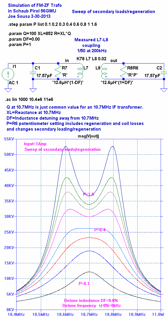
The only significant difference between this alignment and the recommended alignment is that the L7 primary and the L8 secondary are aligned to 10.65MHz and 10.75MHz respectively, instead of 10.7MHz. When the primary and secondary are aligned to the same frequency as shown in the following simulation on the left, a variation in secondary loading or regeneration does not tilt the top of the response; it simply controls the degree of the under- or over-coupled response. The under-coupled response produces a single central peak, while the over coupled response produces twin peaks at identical height. The two LTspiceIV .AC simulations step the value of R6 with the parameter P. (Click the figures to enlarge). The input is an ideal 1Amp source, and the output result in volts can also be directly interpreted as a trans-impedance in Ohms.
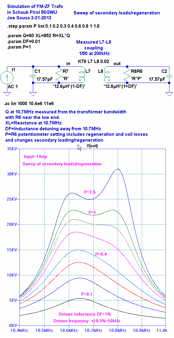 But if the primary and secondary are detuned from each other, as shown in the simulation on the right, then a variation in secondary loading or regeneration will also affect the tilt at the top of the response. The double-tuned transformer affords an extra degree of freedom for alignment, as compared to a single-tuned transformer. With the double tuned transformer, over-coupled response can be maintained for steep skirt selectivity, while the top is adjustable for a slope that drops smoothly by about 50% from one peak to the other. It is not important to chose which coil gets which frequency, as long as they are 100kHz appart and centered with respect to 10.7MHz.
To thank the Author because you find the post helpful or well done.