telefunken: 8001WK; Spitzen-Super
telefunken: 8001WK; Spitzen-Super

Please for help for Telefunken 8001WK repair.
I dont have radio set service documentation, so - its not easy for me.
Question is about connection schemat -- for circuit (frequency) control
This is a photo down of T 8001 WK. Must be rope - but I dont know where....
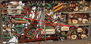
More photos here.. http://zenonas.langaitis.fotopic.net/c928280.html
Please send me photo down of Telefunken 8001WK, who have that radio set, if its impossible.
now I try in germany... :-)
Thank you
Zenonas Langaitis
Lithuania
To thank the Author because you find the post helpful or well done.
Dear collectors, hello Zenonas,
please let me answer in german language at first, because some things are difficult to explain in english for me. You will find the english version at the end of this article later on. Sorry, it will take some time until this post is finished.
Thanks
Andreas
Liebe Sammlerkollegen, hallo Zenonas,
lassen Sie mich bitte zunächst in Deutsch antworten, denn einige Dinge sind für mich in Englisch schwer zu erklären. Eine englische Version werden Sie am Ende dieses Artikels später finden. Es wird leider einige Zeit dauern, bis dieser Post fertig ist.
Danke
Andreas
1. Zenonas fragte, wie der im Bild gezeigte Kondensatorblock original angeschlossen ist. Es handelt sich dabei um den Block mit der Bezeichnung T51684, BV.1002, Lg.Nr.12251, Best.Nr.80359. Dieser Block liegt im Bereich der Röher AF7 (erste ZF-Stufe).
Die Anschlüsse sind wie folgt (alle Angaben beziehen sich auf das Telefunken Werkstattbuch 1938/39):
-Pin 1, schwarz: Masse, Anschluß an den gemeinsamen Massepunkt zwischen den Röhren AF7 und AB1.
-Pin 2, gelb, 0,1µF, Prüfspg. 200V: C113, Kondensator am Fußpunkt des ersten ZF-Filters, Sekundärkreis, Einspeisepunkt der neg. Gittervorspannung über R108 (1,5 MΩ). Anschluß an Lötösenleiste auf Chassishinterwand, obere Reihe, zweiter Lötpunkt von links.
-Pin 3, blau, 0,1µF, Prüfspg. 360V: C114, Kondensator am G2 der AF7. Anschluß direkt an Röhrenfassung.
-Pin 4, Lötöse, 0,1µF, Prüfspg. 900V: C115, Entkopplungskondensator für die Anodenspannung der AF7, Primärseite des zweiten ZF-Filters. Lötöse selbst dient als Verdrahtungsstützpunkt.
-freier Pin, Lötöse: keine innere Verbindung.
-Pin 5, grün, 0,05µF, Prüfspg. 200V: C116, Kondenstator am G3 der AF7. Anschluß direkt an Röhrenfassung.
Als Ergänzung finden Sie Bilder vom betreffenden Schaltungsteil in den Attachments.
2. Zenonas fragte nach dem Verlauf der beiden Zugseile zur Bandbreiteneinstellung. Inzwischen ist ein ganzer Artikel daraus geworden, so daß ich mich entschieden habe, einen neuen Thread zu eröffnen. Hier ist der Link.
Grüße
Andreas Steinmetz
And now the english version (thanks to Alfred Zeeb for his help):
1. Zenonas asked, how the capacitor block - as shown in the picture - is originally connected. The block in question carries the designation T51684, BV.1002, Lg.Nr. 12251, Order Number 80359. The block is located near the tube AF7 (first IF stage).
Connections are as follows (with all information taken from the Telefunken workshop manual 1938/39).
-Pin 1, black: Ground, connected at the shared ground contact between tubes AF7 and AB1.
-Pin 2, yellow, 0.1uF, test voltage 200 V: C113, capacitor at the lower point of the first IF filter, secondary side, feed-in of the plate negative voltage via R108 (1.5MΩ ). Connection at soldering lug bar at the back of the chassis, second lug from left.
-Pin 3, blue, 0.1uF, test voltage 360V: C114, capacitor at plate 2 (G2) of the AF7. Connection directly at the tube socket.
-Pin 4, soldering lug, 0.1uF, test voltage 900V: C115, decoupling capacitor for the anode voltage of the AF7, primary side of the second IF filter. Soldering lug itself serves as wiring support.
-free pin, soldering lug, no internal connections.
-Pin 5, green, 0.05uF, test voltage 200V: C116, capacitor at plate 3 (G3) of the AF7. Connection directly at the tube socket.
Supplementary pictures to this part of the circuitry can be found in the attachments.
2. Zenonas asked for the routing of the two drive wires for the bandwidth/selectivity control. Since that time that theme has become a complete article, so that I decided to open a new thread. Here is the link.
Regards
Andreas Steinmetz
- C113_116_1 (81 KB)
- C113_116_2 (41 KB)
To thank the Author because you find the post helpful or well done.
I think, its can be interesting for other collectors too... Attachments:
- IMG_0130 (38 KB)
- IMG_0131 (34 KB)
- IMG_0132 (91 KB)
- IMG_0133 (74 KB)
- IMG_0135 (70 KB)
- IMG_0136 (57 KB)
- IMG_0137 (54 KB)
- IMG_0138 (52 KB)
- IMG_0140 (63 KB)
- IMG_0141 (92 KB)
- IMG_0142 (84 KB)
To thank the Author because you find the post helpful or well done.
thanks a lot for the pictures. Sorry, but in the pictures there the typical mistakes are made. So the radio will not work properly. Please don´t use the pictures for reference! The right way is more difficult. I have already taken pictures of the interesting details from three different chassis (including the GW-versions), and I am just preparing the description. Please wait...
Regards
Andreas
To thank the Author because you find the post helpful or well done.
I see differences in montage between my radio, and colleque Valerij.
What original variant ? waiting, no problem..
To thank the Author because you find the post helpful or well done.
Liebe Sammlerkollegen, hallo Zenonas,
inzwischen habe ich im Post 2 die Bilder und die englische Version hinzugefügt. Ich hoffe, daß es jetzt mit dem Anschluß des Kondensator-Blockes keine Probleme mehr gibt.
In dem Post habe ich auch berichtet, daß für die Sache mit den Seilzügen zur Bandbreiten-Einstellung einen neuer Thread erforderlich geworden ist. Hier nochmals der Link.
Andreas
Dear collectors, hello Zenonas,
in the meantime I have added pictures and the english version to post 2. I hope that there will not be any problems with the connection of the capacitor-block any more.
In that post I told you that it became necessary to open a new thread for the description of the bandwidth-/selectivity-control. Here the link is again.
Andreas
To thank the Author because you find the post helpful or well done.