Tesla 1.01
Tesla 1.01
Tesla's methods for wireless power transmission with resonant circuits are getting a fresh look at MIT.
So far, it appears that the greatest advance lies in having recognized applications where this kind of short range wireless power transmission would be useful. But recent papers also offer a comprehensive analysis of the fundamental Physics.
A few recent papers have been published, and are freely downloadable. One such paper by authors
Aristeidis Karalis, J.D. Joannopoulos, Marin Soljacˇic
can be dowloaded at
http://www.mit.edu/~soljacic/wireless-power_AoP.pdf
Wikipedia and many other tech-news outlets have published short reports on this topic.
The paper I listed has a very accessible and rigorous treatment of coupling between resonant circuits. It covers Magnetic field coupling between resonant coils and Electric field coupling between resonant dielectric diskss.
This should be an interesting read for those familiar with RF transmitter design, or with IF transformer design.
One of the pictures that shows up on the internet has the authors of the paper sitting between two resonant coupled coils with a lightbulb load. A very similar pose was used by Tesla in well known photographs. These photos inspired the title of this post.
I was able to grasp two key concepts from this paper:
1-The resonant circuits have ratios of E-Field/M-Field, which is to say field impedance, that is either very high, in the case of resonant E-Field transmission, or very low, in the case of M-Field transmission. The reason for this is to keep the ratio of these fields as far way from the impedance of free space as possible (377 Ohms), so that very little energy is radiated and lost. Only a resonant circuit of the same impedance can effectively collect the energy over short ranges. The idea of very high or very low impedance also aims to be as far away from the impedance of obstructing objects as possible. One such object could be the human body.
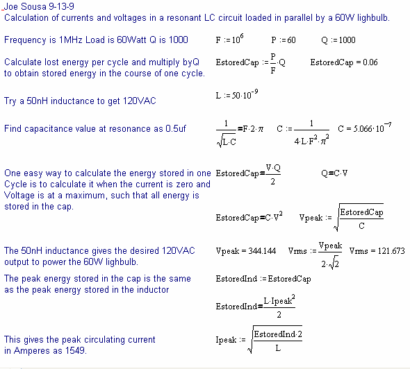
2-All of these resonant circuits run with spectacularly high Q, well above 1000. This is how the very high or very low E/M is created. This means that they store prodigious amounts of energy to deliver relatively modest loads. One way to understand Q is to consider that it is the ratio of stored energy over one oscillation cycle divided by the energy that is lost or dissipated over the same cycle.
One way to understand this power transmission problem is that you want to have very good impedance match between transmitting and receiving circuits, but very strong mis-match of impedance to any surrounding objets, or to free space.
The following is an arbitrary calculation using MathCAD, that illustrates how much current flows in a resonant LC circuit with a 60W load, and loaded Q of only 1000, which is considered low by the authors of the paper listed above. This calculation is arbitrary in the sense that different inductances, capacitances and frequencies may be chosen.
This is an interesting, and very analog, problem. Perhaps the time for this is a method of power transmission has come, albeit over short distances.
Comments invited, in particular with regard to any calculation errors.
-Joe

To thank the Author because you find the post helpful or well done.
