The Sutton tube, the first reflex klystron oscillator
The Sutton tube, the first reflex klystron oscillator

In the early 1940 British had taken the decision to build radio-localization sets operating around 10 cm. At Birmingham a group of scientist leaded by Professor Mark Oliphant was working by 1939 on the development of power klystrons, based upon the tube recently devised by Russell and Sigurd Varian at Stanford. We know that at Birmingham in February 1940 Randall and Boot operated their first prototype of multi-cavity magnetron and it was time to start with microwave designs.
Fig. 1 - A very early klystron prototype, similar to those assembled by the Varian brothers at the Stanford University. Such a tube was the first quite powerful source of microwaves and subsequent experiments were run from 1939 both in America and in Europe. The early microwave sources tried by the group of Prof. Oliphant at Birmingham, before the cavity magnetron of Randall and Boot, were based on similar devices. Click to enlarge
Quite early in 1940 Robert W. Sutton of the Signal School group at the Bristol University started developing a single resonator reflex klystron for the local oscillator of the receiver. Klystron was promising over other microwave sources, magnetrons or Heil oscillators, because of its predictable low noise, due to the loose interaction with the shot noise of the electron beam and to the high ‘Q’ of the output resonator.
A focused CRT electron gun was used to generate the electron beam. To keep low the coupling and hence the noise generated from electrons, the resonator iris of the interaction gap was quite large, about 5 mm. Two deep drawn copper discs formed the horned internal interaction gap, connecting it to the external resonating cavity through a glass-to-copper seal process recently developed at GEC. The reflector was cup shaped, likely to keep the beam still focused in its backward travel. The shape of the internal horns was likely inspired to the Hansen’s rhumbatron resonators and anyway similar solutions can be found in parallel developments, as the linear klystrons made at Bell around the early forties.
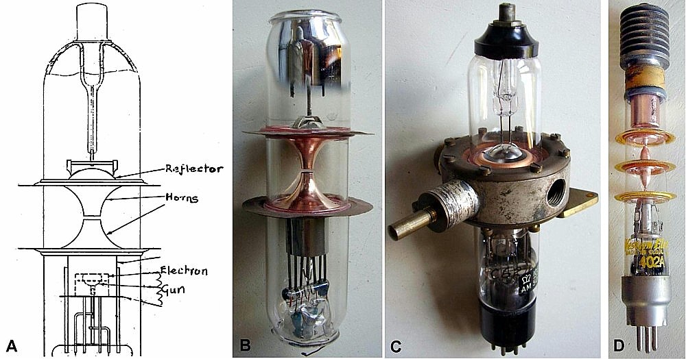
Fig. 2 - A) Draft of the Sutton tube bulb. B) A Sutton bulb believed to come from the Bristol group of Signal School, likely used to perform the necessary tests when designing the external cavities. C) Complete AM 10E/501, S/N 062. This derivative of the Sutton prototypes was made for airborne sets and then tunable in the frequency range matching the frequency of CV38, 3297 MHz. D) A sample of the Western Electric 402A, one of the many linear beam amplifiers experimented at Bell and showing similar deep drawn resonators. Click to enlarge.
According to Callick, the first ‘Sutton tube’ operated in September 1940 with 3% tuning range. Its development with properly operating external cavities was completed by December 1940. Approved by the Admiralty as NR89, it gave about 10 mW in output at 10 cm, with 8% tuning range.
The use of NR89 and its Air Ministry frequency variant 10E/501 was difficult, due to the high resonator voltage, about 1700 V, and to the critical operation through the tuning range. Due to the excessive drift space, there was a tendency of mode jumping. Yet the ‘Sutton tube’ was the only microwave oscillator available until November 1941, when the improved EMI designs, approved as CV35 and CV36, were released for production, soon followed by the Western Electric low-voltage type 707A.
Canadian variants of the ‘Sutton tube’ were made by Rogers for REL from 1941. To prevent the criticism of the variable mechanical tuning, the REL Type 8 klystrons were factory pre-tuned to fixed frequencies, with four frequency suffixes, A to D. Type 8 was ruggedized, with two aluminum half cans supporting the resonator. It was used among the others in the Canadian REL GL3 set, delivered to Great Britain from Autumn 1941.
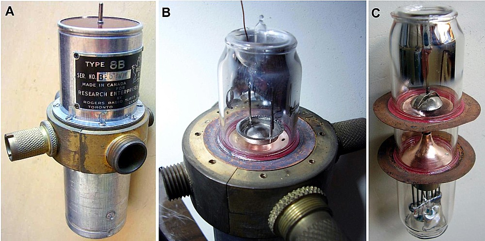
Fig. 3 - The Type 8 Canadian reproduction of the Sutton tube, made by Rogers for REL. The external resonator looks quite simpler than in the original version and supported by two aluminum half cans. The variable tuner has been removed, replaced by factory tuned plungers. Four frequency variants were made, identified by suffixes A to D. In B one sample of REL 8 with top can removed, to show the cup-shaped reflector over the deep drawn upper horn. In C the bulb of the original Sutton tube, to observe the small differences, mainly in the support of the reflector. Click on image to enlarge.
The ‘Soft Sutton tube’, the first TR switch
According to Callick the first TR cell for 10 cm radar systems was designed by A.H. Cole at the Clarendon Laboratory around the mid 1941. To protect the silicon mixer diode against burnouts, TR must ionize very rapidly when the magnetron pulse begins. The use of a high-Q resonator could greatly improve the ionization. NR89 ‘Sutton tube’ with its ‘rhumbatron’ cavity was at the time already in production by EMI and E.K. Cole, so its bulb was readily adapted to the new application. The electron gun and the reflector were removed and the bulb was filled with low pressure water vapour. Several months were required to reach reliable operation. At the end, an electrode similar to the reflector was used as keep-alive electrode, to maintain the tube near to ionization. A small quantity of argon was added to the water vapour, to obtain the required ionization and deionization time and an acceptable operating life.
Although the TR cell was approved as CV43 only at the end of 1942, its design details were sent to America at least one year before. Here WE designed its 702A and 709A, both derived from the resonators structure of Bell linear klystrons.
At the beginning the TR switch was referred to as ‘soft Sutton tube’ because the use of a bulb very similar to that of the ‘Sutton tube’ and of its gas filling, similarly to the very early gas-filled triodes, referred to as ‘soft triodes’. Later versions of CV43 used different resonators, derived from improved klystron designs.
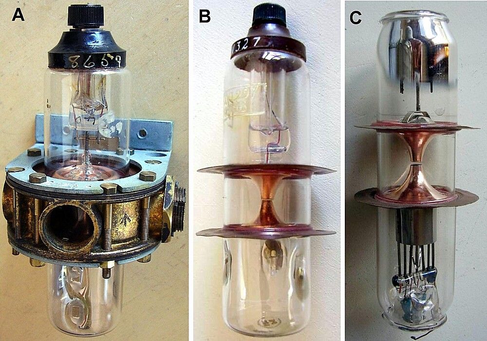
Fig. 4 - CV43 TR was also referred to as ‘soft Sutton tube’, since in it started being built around a depopulated ‘Sutton tube’ filled with water vapour. B) The glass bulb of a TR cell compared with the bulb of a ‘Sutton tube’: the electron gun in missing in the first one, while the reflector is retained to be used as keep alive electrode. Click on image to enlarge.
References:
- Callick, Metres to Microwaves
- Electronics
- Sperry, Klystron Technical Manual
- Direct observations
All the tubes in the photos are from the ase-museoedelpro collection
To thank the Author because you find the post helpful or well done.
Part two: The American challenge and the British response
We know that the Sutton tube operated for the first time in September 1940 and its development, involving the associated external cavities and their coupling to the copper discs protruding from the glass bulb, was completed within December. We also know that the preliminary specs, which British released on October 1940 to Canadian REL for a GL microwave radar, suggested the use of a Northern Electric E1189 for the transmitter and of a Bell Lab subassembly for the receiver using a 1020Y local oscillator and a crystal mixer to be designed. We must assume that the Tizard Mission unveiled to Bell technicians also the latest achievements by the Sutton’s group, waiting for any alternate proposal which could reduce the time of deployment of the microwave radar. We know that, as proposed in the preliminary specs, the exact copy of the E1189 magnetron was produced in volume as REL 3D by Northern Electric, a Canadian company related to Bell. Unfortunately the Bell klystron design was delayed for some reasons and REL had to switch to a Rogers re-design of the Sutton tube, the Type 8, for the local oscillator of the receiver.
In 1941 in England EMI started improving the Sutton design, reducing the diameter of the interaction gap to 2 mm and using a much smaller reflector placed very close to the resonator, to reduce the tendency to mode jumping. According to Callick, the experimental work was completed in June 1941 and first samples of CV35, CV36 and CV67 were released by November. As result, the new oscillators were much more stable, even if still requiring about 1300 V to operate.
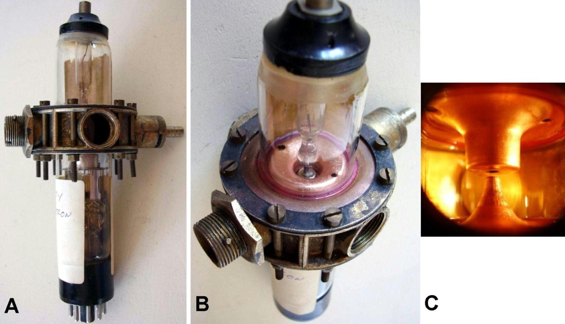
Fig. 5 - Images of an early version of CV35, still with bakelite top spacer. In B) can be observed the small size of the reflector, deeply penetrating into the top end of the resonator. In C) a close-up view of the electrode shapes at the interaction gap. Click to enlarge
By the middle 1941 McNally at Bell Labs had built samples of low voltage klystron tubes. Since the spot noise of electrons could be canceled by a newly conceived balanced diode mixer, the new design approach took advantage of mesh grids to increase coupling between the resonator system and the electron beam. Grids became bright white under the impact of electrons, but the tube was capable of operation at 300 V. Samples of the WE 707A, complete with suitable external resonator, were released only by the end of 1941, few days after the delivery of the renewed EMI klystrons. The announcement of the new WE klystron certainly caused considerable disappointment in England.
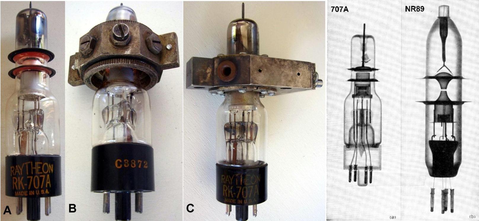
Fig. 6 - Samples of 707A, two of which with different resonating cavities installed. On the right the X-ray photo of the WE 707A compared with that of the British NR89, source Bell Labs. Click to enlarge.
As soon as news and likely also samples of the new 707A arrived in England, TRE requested the development of a new family of oscillators capable of operation under 300 V. The design of KR6 family was carried out by EMI with assistance from the group of Signal School at Bristol, the same who had designed the very first Sutton tube. Moving from samples of WE 707A, the group built some intermediate experimental units, one of which is in figure 7 below. They devised a grid made of thin corrugated tape, about 1 mm high, welded to the internal ribs of the resonator.

Fig. 7 - A rare sample of an experimental klystron built at Bristol during the development of the low voltage EMI KR6 family. The shape of the tube recalls that of a 707A. The grid of the prototype, made of corrugated tiny ribbon, can be barely seen in the photo at top right. On the bottom, the grid of a production klystron, the CV237. Click to enlarge.
The new KR6 design led to the frequency variants, CV116, CV237, CV238 and CV272. They well outperformed the American design, being considerably smaller in size and operating at 230 V resonator, the same supply voltage of the IF section. They also offered an indubitable ease of in field replacement, since all the British klystrons came with factory installed and pre-tuned resonator system.
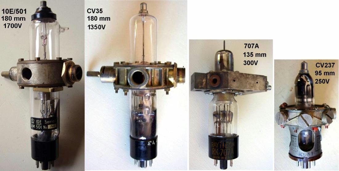
Fig. 8 - Evolution of the 10-cm local oscillator in the years from 1940 to 1943. The Sutton tube was ready by the end of 1940. The 10E/501, together with the frequency variant NR89, was made through 1941. The CV35 and its frequency variants were delivered by November 1941. The WE 707A was delivered by December. The CV237/CV238 are frequency variants of KR6, whose development started in mid 1942 and ended in May 1943. Click to enlarge.
The British packaged solution was appreciated by Raytheon which introduced its own line of 10-cm packaged klystron oscillators, based upon 707A/B tubes or upon the improved variant 2K28.
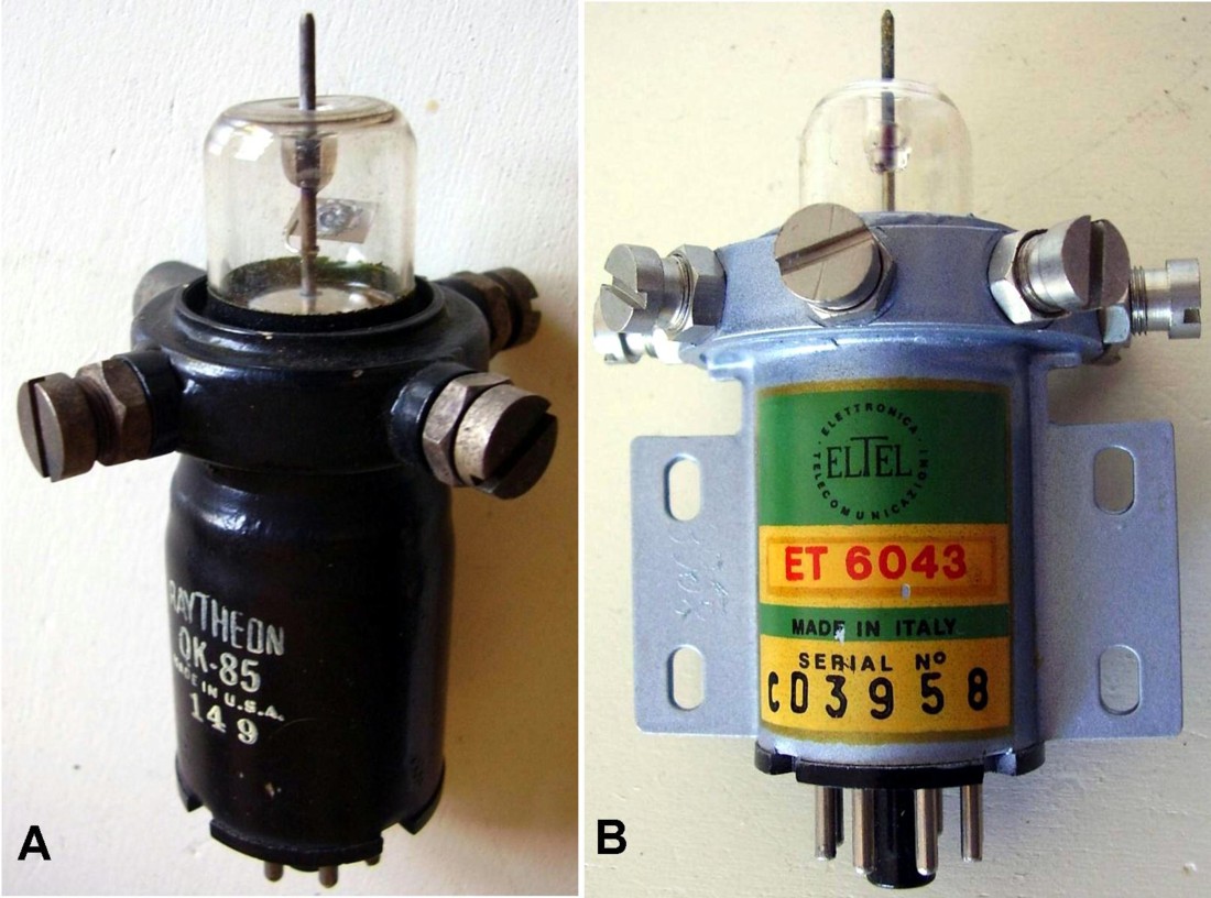
Fig. 9 - Two Raytheon packaged klystron oscillators. Both QK-85 and 6043 were variants of 2K28, with factory installed resonator. The sample in the right photo was made by ElTel, formerly ELSI which in the early sixties was a qualified Raytheon plant in Palermo, Italy. Click to enlarge.
Anyway the ‘Sutton tube’ and its direct derivatives were used just in the early quasi-experimental steps of 10-cm radars, through 1941. One year later, when the CV register was activated, just two entries were left of the ‘Sutton’ early tubes, CV10 and CV11, not even a description. Titles had been allocated respectively to NR89 and to 10E/501 but ‘Sutton tubes’ were already obsolete and forgotten until today.
References:
- Callick, Metres to Microwaves
- Hamilton et al, Klystrons and Microwave Triodes
- Knowles Middleton, Radar Development in Canada
- Southworth, Principles of Waveguide Transmission
- Direct observations
All the tubes in the photos are from the ase-museoedelpro collection
To thank the Author because you find the post helpful or well done.