unknown: LW/MW SG4 kit: Restoring coils
unknown: LW/MW SG4 kit: Restoring coils
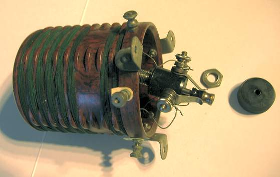
The coils wave change switches were seized. As well as fixing the switches I worked out the wiring and measured the inductances in MW & LW mode. This shows the coils and switches are working and the wiring is actually correct.
Information on the coils is below the photos. Heat from gas stove and hammering was needed to free the switch shaft in the "collet" / outer barrel on both.
The first RF stage (V1, the RF SG/Tetrode S210_Tungsram or possibly an SG215) has 8 windings and the second RF stage has an additional pair of windings for "tickler", the coil connected to anode via a capacitor for regenerative feedback on V2, HL210 (triode recommended for Detector or LF preamp).
RF Coil unit 1
Three connections are labelled 3, 5 & 6. Functions according to existing wiring:
Common / 0V / HT- / LT- / Earth : 3
Tuning capacitor / grid : 6
Aerial via capacitor : 5
I have arbitrarily referred to unused connection between 3 & 5 as 2 and beside 6 as 4.
Pulling up the switch is MW and shorts 2 , 4 & 5, pushing down is LW. The unlabelled connections I have called 2 & 4 are obviously for front panel Wavechange switching along with 5 which is aerial input via a capacitor.
Inductances after switch repair.
| Term | LW | MW |
|---|---|---|
| 3 - 5 | 1mH | 51uH |
| 3 - 6 | 2.9mH | 148uH |
| 5 - 6 | 1mH | 50uH |
| 6 - 4 | 54uH | 49uH |
| 3 - 2 | 57uH | 51uH |
| 2 - 4 | 2.5mH | 1uH |
Coil layout on former.
The top 6 windings connect a top to 2 and bottom to 4, the centre tap is 5. There is then a gap of two "windings" and the next coil is on 2 and 3. The last coil is 4 & 6. The connections in bold have two winding connections.
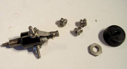
Repair of switches


Now we can heat and hammer the innner shaft in outer barrel to free it.
Overnight soak in WD40 didn't work!


RF Coil unit 2
Four connections are labelled 3, 4, 5 & 6. Functions according to existing wiring:
Common / 0V / HT- / LT- / Earth : 3
Tuning capacitor / grid via capacitor : 5
Input from V1 anode via capacitor : 1
Feedback regeneration to V2 anode via Regeneration variable capacitor : 6
I have arbitrarily referred to unused connection between 5 & 6 as 4 (beside 5) & 2 (beside 6).
Pulling up the switch is MW and shorts 2 , 4 & 1, pushing down is LW. The unlabelled connections I have called 2 & 4 are obviously for front panel Wavechange switching along with 1 which is input via a capacitor.
Inductances after switch repair.
| Term | LW | MW |
|---|---|---|
| 1 - 3 | 1mH | 60uH |
| 1 - 5 | 1mH | 55uH |
| 3 - 5 | 3mH | 165uH |
| 1 - 6 | 1mH | 178uH |
| 5 - 6 | 3.5mH | 338uH |
| 6 - 3 | 119uH | 1uH |

Conclusion
The tricky bit was fixing/freeing the wavechange switches. Thanks to those folk that suggested the wavechange switches likely built in.
Aluminium (or copper, brass etc) screening cans would be very large as ideally the can wall should be spaced a radius out from edge of coil!
The wire appears to be solid single strand rather than "Litz" and cotton covered, cheapskates! Lovely Bakelite formers. The layout isn't what I would have thought of! No wonder the Mullard "Wireless for the million" magazines usually show a simplified coil and note that wave band switching is omitted for simplicity of understanding the circuit.
Reverse Engineering
With the coils "mapped" out a schematic is possible. So I have uploaded a sketch of it, I added missing earth on the C2 & C4 (large paper capacitors), swapped the side of HFC L10 that C4 was connected to and connected C3 to V1 anode. That was the three missing wires and one wiring error.
Unfortunately the Primaries on both "inter-stage" audio transformers are open circuit. These are very fragile and could have been burnt out by lack of grid bias. V2 HL210 "grid leak" resistor R1 is intermittantly 6M Ohm to open circuit (> 20 M Ohm), it's usually about 2M ohms.
To thank the Author because you find the post helpful or well done.