zenith: ; 702
? zenith: ; 702

Dear collegues,
I found in a deplorable situation a radio device Zenith 702 made in 1934 – in
I bought from
In the drawing attached , the most resistances are marked with M character. Does somebody knows what this mark represents?
Under the chassis , fixed on the wall with caps, is a wire wound resistance , wich, unfortunately is destroyed. Does somebody knows the value of this resistance and the wats, also its position in the drawing?
I am asking Mr. BIRKNER to reply, because I saw that he has a Zenith 702.
Best regards,
Ion Carabas (e-mail address: ion.carabas@coneco.ro) .
- Electrical schematic (87 KB)
To thank the Author because you find the post helpful or well done.
? '. M' = K Ohms

If you could post a picture of the chassis and the part you need to ID, it would be a big help.
The point before the M has gone lost in the schematic ...
.M (with the point) would be correct for Kiloohms but better and more often used is k or K - and we see here why ...
To thank the Author because you find the post helpful or well done.
? 702 unknown resistor

Please trace the connections of the resistor to other elements, e.g. tube pins. That should result in a clear allocation in the schematic and consequently the values.
I am currently not in the position to dismantle the set
Good luck,
KoBi
To thank the Author because you find the post helpful or well done.
Please upload pictures of the wiring - yet untouched

It is always a big help if members load up photos of the wiring of an untouched set after dismantling. Explanations are then much easier.
Maybe you have not yet changed things and can do so?
Zenith 702 seems having schematic variants.
The official Zenith schematic differs from that we show and possibly also from the Rider's. In case of need I can scan and upload the Rider's schematic. Our SchematicFinder tells us that it is Rider's volume 5 page Zenith 4. I have all of them - but not necessarily the time to help in any case - just if it is necessary.
There are only a very few possibilities for this wire wound resistor (which can be within a small shielded case) but since we don't want to guesswork (cathode resistor of the 75 - if having only two wires), we better wait for the photos - which might help later for other guests or members.
To thank the Author because you find the post helpful or well done.
Zenith 702 - reply
Dear Mr. Ernst,
I have to confess that I did not espect for help so soon from the collegues from Radiomuseum. I had the sensation that I am in a family, emotion wich gave me a spiritualy calm. I will prepare urgently photos.
Thank you,
Ion
To thank the Author because you find the post helpful or well done.
new manuals
Hello Ion,
please read my new thread about the resistors. It makes sense to crop the pictures before reducing to 933 pixel. So you can show more details. Please loade your best pictures direct to the model page.
Regards,
Heribert
To thank the Author because you find the post helpful or well done.
Zenith 702
This AC/DC set originally had a resister cord to drop the line voltage to the proper level for the filament string. The old destroyed part on the side of your set is (was) a candohm resister, that was probably part of an earlier attempt to do away with the resister cord so that a modern type input cord could be used.
It is pretty common to run into this with these older sets with resister cords. They can be quite dangerous (fire hazard) with the higher voltages we use today. They were built for 110 volts, but usually today you will get 120 volts and up to 130V. That's too much for those old cords, and they will over heat.
The large gold resister seems to be a replacement for the destroyed candohm resister. It appears to be between the on/off switch and the filament string. The purpose would be to drop line voltage in place of the resister cord.
If you could check the line cord for it's resistance value, that should verify this theory. If it has little to no resistance, then we are on the right track. If it is 145 ohms, then the old resister cord is still in place, and we need to go another direction.
To thank the Author because you find the post helpful or well done.
Material for resistors
Dear Heribert,
Please tell me where I shall search your material about resistors. In the nearest future I will crop the photos. Please be understable with me, because I manage hard with the computer, because I am 73 years old.
Thank you,
Ion Carabas
To thank the Author because you find the post helpful or well done.
M in US schemas or in German schemas
Dear Ion,
you find my info under the model.
Regards, Heribert
To thank the Author because you find the post helpful or well done.
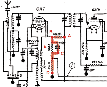
702
The element in question contains two resistors of 75oo Ohm and 250 Ohm resp., and a capacitor of 0.05 µFas follows:
A - B = 7500 Ohm
B - C = 0.05 µF, in parallel a 10 kOhm resistor E
C - D = 250 Ohm (schematic says 200 Ohm).
Point D is chassis
Note: the cap is not directly connected with chassis ground, as suggested by the schematics!

Here is the configuration as found in my 702 (compare with the "official" schematic):
Good luck
KoBi
To thank the Author because you find the post helpful or well done.
Zenith 702 -thank you
Dear Kobi,
Now everything is clear. Thank you and I wish to you healthy.
Ion
To thank the Author because you find the post helpful or well done.
Zenith schematic
Thank you for the schematics.
I observed that something is missing and that is the value of the condenser marked with the green circle.
Attachments:- Zenith 702 (105 KB)
To thank the Author because you find the post helpful or well done.
Capacitor
Standard value is 50 pF for this part.
To thank the Author because you find the post helpful or well done.