- Produttore / Marca
- Zenith Radio Corp.; Chicago, IL
- Anno
- 1934
- Categoria
- Radio (o sintonizzatore del dopoguerra WW2)
- Radiomuseum.org ID
- 19015
-
- alternative name: Chicago Radio Lab


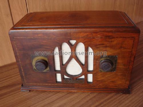
Knobs are not original.
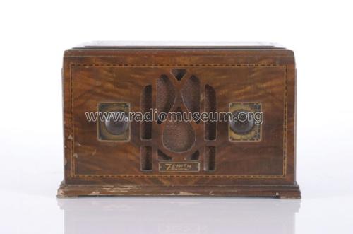
From an auction catalogue.


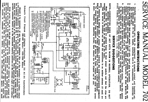
Operating instructions


Clicca sulla miniatura dello schema per richiederlo come documento gratuito.
- Numero di tubi
- 5
- Principio generale
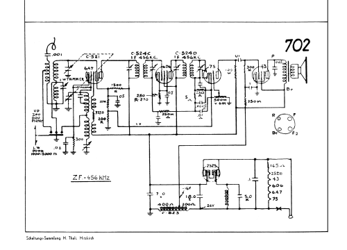
- Supereterodina (in generale); ZF/IF 456 kHz
- N. di circuiti accordati
- 6 Circuiti Mod. Amp. (AM)
- Gamme d'onda
- Onde medie (OM) e onde lunghe (OL).
- Tensioni di funzionamento
- Alimentazione universale (doppia: CC/CA) / 115 Volt
- Altoparlante
- AP elettrodinamico (bobina mobile e bobina di eccitazione/di campo)
- Materiali
- Mobile in legno
- Radiomuseum.org
- Modello: 702 - Zenith Radio Corp.; Chicago,
- Forma
- Soprammobile compatto/con bordi arrotondati/midget senza pulsantiera/tastiera.<= 35 cm (Sometimes with handle but for mains only).
- Dimensioni (LxAxP)
- 300 x 190 x 140 mm / 11.8 x 7.5 x 5.5 inch
- Fonte esterna dei dati
- E. Erb 3-907007-36-0
- Riferimenti schemi
- Rider's Perpetual, Volume 5 = ca. 1934 and before
- Altri modelli
-
In questo link sono elencati 4519 modelli, di cui 4111 con immagini e 3656 con schemi.
Elenco delle radio e altri apparecchi della Zenith Radio Corp.; Chicago, IL
Collezioni
Il modello 702 fa parte delle collezioni dei seguenti membri.
Discussioni nel forum su questo modello: Zenith Radio Corp.;: 702
Argomenti: 4 | Articoli: 17
Dear Forum members,
a friend of mine told me that he had radio that is totally identical to the Zenith 702. The only differend ce is the label Windsor at the front panel, instead of the label Zenith. Please look at the pictures.
At the bottom of the Winsor is the same yellowish paper with the instructions.
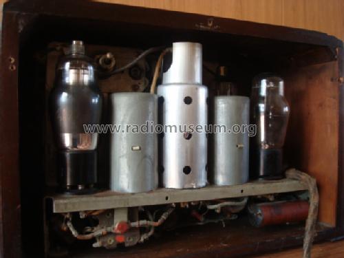
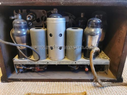
Th set has also an non original power resistor of 150 Ohms, in series with the heaters.
Allegati
- Twee broertjes 100 (214 KB)
- Twee logo's 100 (201 KB)
- Inwendig 100 (230 KB)
Georges Van Campenhout † 28.4.22, 12.Aug.21
I loaded an other schema and a service manual to the model.
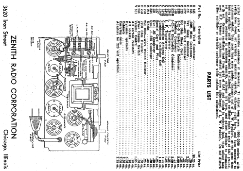
M stands in old US shemas for Mille. See Wikipedia: Mille, the number one thousand, derived from Latin. Kilo is also thousand. So Bryan is right: M means kΩ. = 1 000 Ohm
In German schemas M stands for Meg. = 1 000 000
Heribert Jung, 10.Nov.10
Dear collegues,
I found in a deplorable situation a radio device Zenith 702 made in 1934 – in
I bought from
In the drawing attached , the most resistances are marked with M character. Does somebody knows what this mark represents?
Under the chassis , fixed on the wall with caps, is a wire wound resistance , wich, unfortunately is destroyed. Does somebody knows the value of this resistance and the wats, also its position in the drawing?
I am asking Mr. BIRKNER to reply, because I saw that he has a Zenith 702.
Best regards,
Ion Carabas (e-mail address: ion.carabas[A*T]coneco.ro) .
Allegati
- Electrical schematic (87 KB)
Ion Carabas, 05.Nov.10
Konrad Birkner † 12.08.2014, 29.Dec.03