
25Z5

|
Variants
|
|||||||||||||||||||||||||||||||||||||||||||||||


|
Hits: 5697 Replies: 4
25Z5 used as detector in one-tube set
|
|
|
Georg Richter
16.May.10 |
1
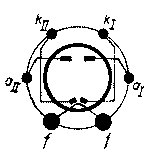
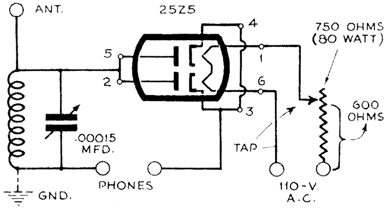
Even if the 25Z5 is extremely underheated - here we are with a project issued earlier by "Popular Science Monthly" and later in the book "Radio For The Millions", extracted from page 133 of the 3rd print of 1946: One-Tube Receiveruses rectifier as detectorBased on a novel and simple one-tube circuit, operating on the house current, this new type of radio receiver brings in stations as clearly as a crystal set, with absolutely no hum, and with fine selectivity and sensitivity. Using a rectifier as a detector tube, no filtering system is needed because no plate voltage is used! The A.C. voltage is needed only to heat the filaments of the 25Z5, with no connections between the A.C. line and the receiver proper. The 25Z5 acts as a diode and has its two plates and cathodes tied together. The plates are connected to the fixed plates of the .00015-mfd. tuning condenser, to the four-prong coil, and to the antenna. The cathodes are connected to the moving plates of the condenser and to the other end of the grid winding on the coil. The phones are placed in the cathode circuit of the tube. The rectifier heater voltage must be adjusted critically to from five to six volts, instead of the rated 25, for satisfactory operation. As there is no line cord on the market rated at 600 ohms, use an 80-watt fixed resistor with an adjustable tap. Otherwise connect two 300-ohm line cords in series.
The complete receiver with it's tube removed
The close-up view shows how the four main parts are placed
Bottom view, revealing the extremely simple wiring of the set
Only the heater uses power, so a ground may be safely used
LIST OF PARTSTuning condenser, .00015 mfd. Today a little mains transformer is better instead to waste about 30W in heat ... Best Regards, GR |
|
Konrad Birkner † 12.08.2014
16.May.10 |
2
G.R. cnfirmed my suspicion of being this possibly an April fool. The "Popular Science Monthly" issue in question is obviously from April 1941... But surprise: I used my SSTRAN 3000 for a quick test, and varied the coupling to a simple crystal set (similar to the one in the article) by its antenna wire and use of a small wideband amp. to provide two different RF levels at the antenna input: 0.3 or 10 mVrms. The set was tuned to the station and several different filament supply voltages (DC) applied. An Oscilloscope served for level estimation. The audio level was taken at the 4 kOhm headphone load: All levels were found by estimation of scope display. Conclusion: it is always good to have a second look..... and sometimes another second (or third ?) look again. You live and learn... KoBi |
|
Emilio Ciardiello
18.May.10 |
3
Dear George and Konrad, Emilio |
|
Konrad Birkner † 12.08.2014
19.May.10 |
4
Dear Emilio, I think there is hardly an advantage: such a circuit increases the damping of the resonant circuit by the lower impedance (higher load) of the demodulator. Lower Q and higher efficiency are more or less kept in balance. There is no benefit in using a doubler or other full wave demodulator. Careful impedance matching would certainly be more efficient. |
|
Joe Sousa
20.May.10 |
5
Gentlemen, The pursuit of a very sharp non-linearity for the purposes of detection was a central concern in the early days of wireless, until RF gain could be done with triodes, or, perhaps, Lieben valves. The RF gain could make the signal arbitrarily large to make the detector sufficiently non-linear with respect to signal amplitude for detection. Increased RF signals were also realized in regenerative detectors, where the RF signal was regenerated with a narrow(ing) bandwidth. This narrow bandwidth was commensurate with audio bandwidth. So, this diode detection topic is rich and interesting. Some of it was explored a while back in a very interesting survey of early diode detection by Hans Knoll. At the time, I contributed post #6 with particular reference to impedance. As Konrad asserts, Impedance dominates the pursuit of detection efficiency. However, there is no single best solution for all diode detection problems. For example, if the load impedance is the very high 10Meg input load impedance of an audio triode preamp stage, then it may not be possible to transform all available RF energy to have a voltage to current ratio around 10Meg. This is one case where a voltage doubler could be used to get closer to the 10Meg load. The doubler could usefully double the output voltage, where other means had been exhausted. The voltage doubler may even improve (reduce) the level of the smallest detectable RF signal, as the detected output of the first diode helps to forward bias the second diode, which has the very light 10Meg load. A similar case could be made in the opposite direction, if the most efficient earphone that could be designed had a very low impedance, like 1Ω. In this case, more than one diode in some clever impedance lowering arrangement may help where RF and audio transformation may cease to be practical. ------------The 25Z5: The thing that may be most useful to find out about the 25Z5, or any other detection diode, is it's I/V characteristic. It should turn out that the best adjustment of heater power is when the average impedance during an RF cycle matches the surrounding source and load impedances. Optimum detection occurs when the impedance of the detector varies the most from the average value at the peaks and troughs of the RF sinewave. Another thing to keep in mind that is unique to all thermionic detectors, is that they spontaneously produce a voltage that makes the cathode more negative than the anode by hundreds of mV, depending on tube design and cathode temperature. This spontaneous thermionically generated voltage is very important to consider because, when loaded with a DC resistance, usually lowers the internal impedance of the diode to be much lower than the load resistor. A 10Meg DC load on a thermionically generated -500mV at the cathode may very well produce a diode current flow and internal impedance that is only 1Meg. This illustrates the concept of self bias. A curve tracing of the 25Z5 would show the actual internal resistance as a slope on the curve. On a related topic, one of the essential design considerations of the value of the well known "grid-leak" resistor is to take advantage of the thermionically generated voltage at the grid of a triode, to set a grid current flow that operates the grid at optimum impedance. The spontaneously generated voltage is particularly convenient replacement for an external battery that was often used in pre-triode solid-state detectors. REgards, -Joe |


|
Hits: 4404 Replies: 0
25Z5 (25Z5)
|
|
|
Reinhard Hanschke
14.Aug.07 |
1
Neupreis 1938: 53,00 FFR. Lit.: Catalog der Fa. MANUFRANCE (MF) von 1938. |
End of forum contributions about this tube
| Data Compliance | More Information |