- País
- Estados Unidos
- Fabricante / Marca
- Admiral (brand) Continental Radio & Television Co.; Chicago, IL
- Año
- 1949
- Categoría
- Radio - o Sintonizador pasado WW2
- Radiomuseum.org ID
- 31345
-
- alternative name: Continental Radio & TV


Sales Brochure
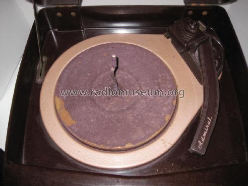
Admiral 6V12 (RC180 record player)

Haga clic en la miniatura esquemática para solicitarlo como documento gratuito.
- Numero de valvulas
- 6
- Principio principal
- Superheterodino en general; ZF/IF 455 kHz; 2 Etapas de AF
- Número de circuitos sintonía
- 6 Circuíto(s) AM
- Gama de ondas
- OM (onda media) solamente
- Especialidades
- Tocadiscos-autom o no-no sabemos
- Tensión de funcionamiento
- Red: Corriente alterna (CA, Inglés = AC) / 117 Volt
- Altavoz
- Altavoz dinámico (de imán permanente)
- Material
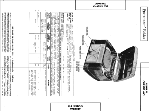
- Plástico moderno (Nunca bakelita o catalina)
- de Radiomuseum.org
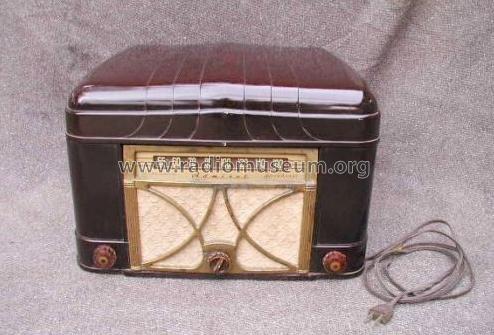
- Modelo: 6V12 Ch= 6V1 - Admiral brand Continental
- Forma
- Sobremesa de cualquier forma, detalles no conocidos.
- Anotaciones
- Color=Mahogany
- Ext. procedencia de los datos
- Ernst Erb
- Procedencia de los datos
- Collector's Guide to Antique Radios 4. Edition
- Referencia esquema
- Rider's Perpetual, Volume 20 covering 1950
- Otros modelos
-
Donde encontrará 3229 modelos, 1333 con imágenes y 2599 con esquemas.
Ir al listado general de Admiral (brand) Continental Radio & Television Co.; Chicago, IL
Colecciones
El modelo 6V12 es parte de las colecciones de los siguientes miembros.
Contribuciones en el Foro acerca de este modelo: Admiral brand: 6V12 Ch= 6V1
Hilos: 1 | Mensajes: 1
Some is so natural, allthough I would like to remind a methode here, which it used already from the beginning of radio history, particulary maintained in the USA, for a much measuring methode-counted.
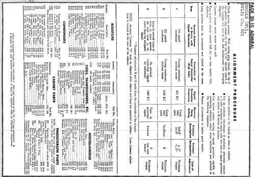
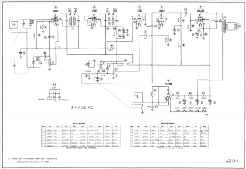
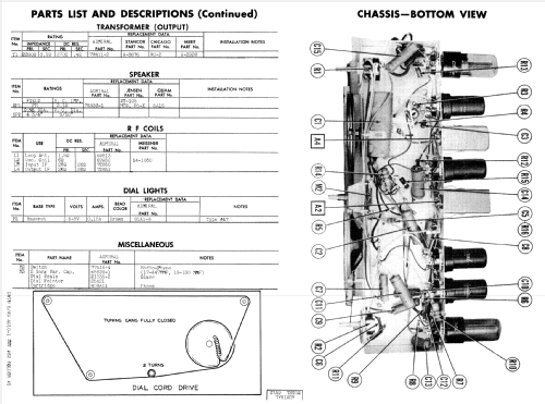
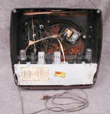
In the documents one finds e.g. shown for this Model ADMIRAL 6V12 these informations:
Under the schematic on the left side the table shows the voltage values, the radio is in working condition. On the right side the table shows the resistance values can measured on several pin of the tubes- the radio is unplugged.
.png)
Ω
.png)
I was classified and from there only rarely used this measuring methode with the Ohm meter, but using this procedure is so simply and it is a quick way to find troubles. The resistance examination shows immediately distinctive features. But some conditions have to be respected, e.g. here see the note ..measured from the pin 8 of V6 - this the central point of the positiv DC-voltage supply.
e.g. Tube 12SA 7 is unplugged
Pin 1 n.c. 160kΩ against chassis
Pin 2 heating pin 36Ω against chassis
Pin 3 Anode measuring the sum of R13, R14 and R15 against pin 8 of V6
Pin 4 Grid 4 measuring the sum of R13, R14 and R15 against pin 8 of V6
Pin 5 Grid 1 measuring 22kΩ this is value of R3 against Chassis
Pin 6 Cathode measuring the low impedance of 0.8Ω against - a part of the coil L2
Pin 7 heating pin 24Ω against chassis
Pin 8 Grid 2 measuring 1.3MΩ (app. R5) against Chassis
Checking the voltage conditions this is the next step, but it is more needed to go in details of the schematic.
For the case, some part is broken or in bad condition the value of voltage gives not directly a clear picture of the given fault. Checking the resistance conditions is a quicker methode for trouble shooting.
Anexos
- USA_admiral 6V12 schematic (174 KB)
Friedrich Weber † 12.09.2014, 15.Oct.13