- País
- Australia
- Fabricante / Marca
- Amalgamated Wireless (Australasia) Ltd. (AWA); Sydney
- Año
- 1939
- Categoría
- Radio - o Sintonizador pasado WW2
- Radiomuseum.org ID
- 171378
Haga clic en la miniatura esquemática para solicitarlo como documento gratuito.
- Numero de valvulas
- 4
- Principio principal
- Superheterodino en general; ZF/IF 460 kHz; 2 Etapas de AF; Reflex
- Número de circuitos sintonía
- 7 Circuíto(s) AM
- Gama de ondas
- OM (onda media) solamente
- Tensión de funcionamiento
- Baterías recargables o pilas / 6 & 4 & -1.5 & -4.5 Volt
- Altavoz
- Altavoz dinámico (de imán permanente)
- Material
- Madera
- de Radiomuseum.org
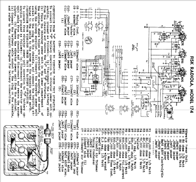
- Modelo: Radiola 174V - Amalgamated Wireless
- Forma
- Consola baja, patas más cortas del 50%.
- Anotaciones
- This set uses a 4 volt synchronous vibrator power unit. The filaments are connected in parallel across one cell of the 6 volt battery and the vibrator power unit is supplied from the other two cells. The 1K7G is reflexed as the 2nd I.F. amplifier and the 1st A.F. amplifier.
- Referencia esquema
- Australian Official Radio Service Manual Vol. III
- Documentación / Esquemas (1)
- Radio & Electrical Retailer, Australia (9/7/42 P10 Also in Mingay's Radio Diagram & I.F. Index)
- Autor
- Modelo creado por Stuart Irwin. Ver en "Modificar Ficha" los participantes posteriores.
- Otros modelos
-
Donde encontrará 1438 modelos, 884 con imágenes y 466 con esquemas.
Ir al listado general de Amalgamated Wireless (Australasia) Ltd. (AWA); Sydney