RMD900/RMD1500/RMD1800 Series of digital radio links.
Amalgamated Wireless (Australasia) Ltd. (AWA); Sydney
- Pays
- Australie
- Fabricant / Marque
- Amalgamated Wireless (Australasia) Ltd. (AWA); Sydney
- Année
- 1986
- Catégorie
- Emetteur / récepteur commercial (TRX non amateur)
- Radiomuseum.org ID
- 321995
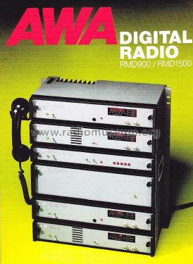
The RMD Series of digital radios brochure.
Cliquez sur la vignette du schéma pour le demander en tant que document gratuit.
- No. de transistors
- Semi-conducteurs présents
- Semi-conducteurs
- Principe général
- Super hétérodyne avec étage HF
- Gammes d'ondes
- Bandes en notes
- Tension / type courant
- Alimentation Courant Continu (CC) / 24V - 50 Volt
- Haut-parleur
- HP dynamique à aimant permanent + bobine mobile
- Matière
- Boitier métallique
- De Radiomuseum.org
- Modèle: RMD900/RMD1500/RMD1800 Series of digital radio links. - Amalgamated Wireless
- Forme
- Rack
- Remarques
-
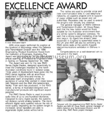
The RMD Series of digital radios were designed specifically to meet the challenges Imposed by the harsh Australian conditions, Including extremes of temperature as well as distance. Telecom Australia was one of the first customers, placing orders in excess of $5 million.
The radios were designed to provide communications into areas very difficult to service because of remoteness and harsh conditions. They coped well with heat and cold, having an operational range over temperatures from 10° to 60°C. Also, they consume very little power, enabling them to be solar powered and to be located in simple shelters which results in large savings In Infrastructure costs.
The equipment provided 900 MHz, 1500 MHz and 1800MHz, 2 to 8 Mbit/s communication links in rural telephone networks, on pipeline projects and major utilities such as power and rail authorities. Repeaters were available that could extend the path lengths over virtually any distance.
The AWA Defence & Transmission Division won the 1986 Engineering Product Excellence Award from the Institution of Engineers Australia for this product.
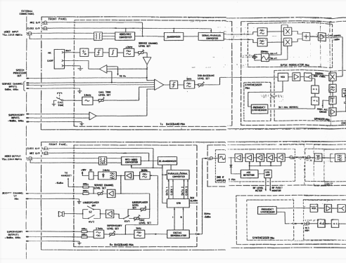
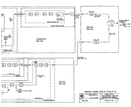
The basic system comprised a transmitter, diplexer, and receiver at each end.The system could be installed in an unprotected mode or equipped with warm or hot standby. Hitless switching is available and enables the system to be configured with either space or frequency diversity. The equipment used line code HDB3 (High-Density Bipolar Order 3) for transmission over G.703 E1 networks.In all configurations a Technicians communication telephone (Order Wire) was proved in a sub-baseband channel and monitored with a speaker in the RX unit.
System Equipment Details
MODEL BAND CAPACITY 902 900 MHz 2 MBit/s 904 900 MHz 4 MBit/s 1502 1500 MHz 2 MBit/s 1504 1500 MHz 4 MBit/s 1804 1800 MHz 4 MBit/s 1808 1800 MHz 8 MBit/s Protection switching is provided by the PSD unit designated by capacity.
MODEL CAPACITY PSD2 2 MBit/s PSD4 4 MBit/s PSD8 8 MBit/s An RF Repeater is available for each frequency band.
MODEL BAND RMR900 900 MHz RMR1500 1500 MHz RMR1800 1800 MHz Equipment Details
The nominal RF output power of the RMD TX was +37 dBm. When power usage was of concern, i.e. solar sites, the power could be adjusted in the range of +30 to +37 dBm.
The TX and RX were both fully agile over the operating band with the frequency being set by screwdriver adjustable decade switches.Monitoring of RF level, BER, fault conditions were available on a display on each unit.
- Littérature
- - - Manufacturers Literature (AWA RMD Series DRS, 000 188-W37)
- Auteur
- Modèle crée par Gary Cowans. Voir les propositions de modification pour les contributeurs supplémentaires.
- D'autres Modèles
-
Vous pourrez trouver sous ce lien 1438 modèles d'appareils, 884 avec des images et 466 avec des schémas.
Tous les appareils de Amalgamated Wireless (Australasia) Ltd. (AWA); Sydney