VCM 163, Valve Characteristic Meter V.C.M. 163
Avo (Brand), Automatic Coil Winder and Electrical Equipment Co., Avo Ltd; London
- Anno
- 1966

- Categoria
- Strumento da laboratorio
- Radiomuseum.org ID
- 100287


Clicca sulla miniatura dello schema per richiederlo come documento gratuito.
- Numero di transistor
- 6
- Gamme d'onda
- - senza
- Tensioni di funzionamento
- Alimentazione a corrente alternata (CA) / 110-240 Volt
- Altoparlante
- - - Nessuna uscita audio.
- Materiali
- Mobile di metallo
- Radiomuseum.org
- Modello: VCM 163, Valve Characteristic Meter V.C.M. 163 - Avo Brand, Automatic Coil
- Forma
- Soprammobile a leggio (pannello inclinato).
- Dimensioni (LxAxP)
- 460 x 350 x 365 mm / 18.1 x 13.8 x 14.4 inch
- Annotazioni
-
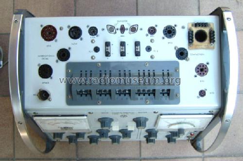
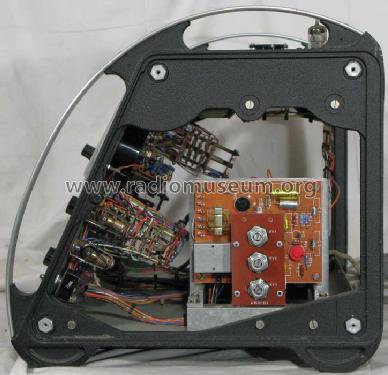
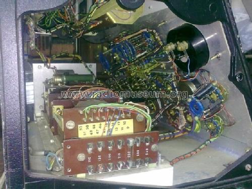
Contains 14 Valve bases, two large measurement instruments.
- Fonte dei dati
- -- Schematic
- Autore
- Modello inviato da Georges Van Campenhout † 28.4.22. Utilizzare "Proponi modifica" per inviare ulteriori dati.
- Altri modelli
-
In questo link sono elencati 86 modelli, di cui 83 con immagini e 41 con schemi.
Elenco delle radio e altri apparecchi della Avo (Brand), Automatic Coil Winder and Electrical Equipment Co., Avo Ltd; London
Collezioni
Il modello VCM 163, Valve Characteristic Meter fa parte delle collezioni dei seguenti membri.
Discussioni nel forum su questo modello: Avo Brand, Automatic: VCM 163, Valve Characteristic Meter V.C.M. 163
Argomenti: 2 | Articoli: 7
Tube Tester AVO V.C.M. 163 – Measurement principle of plate/screen current and mutual conductance
by Kurt Schmid (DH3PJ) Mainz, Germany
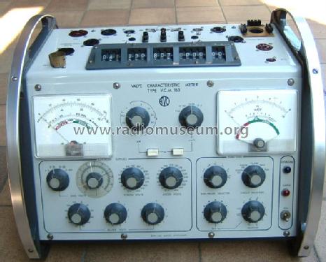
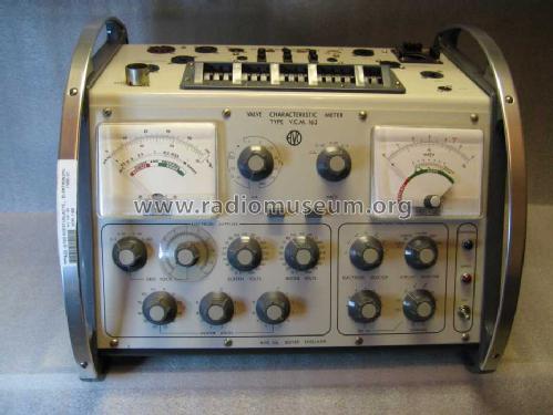
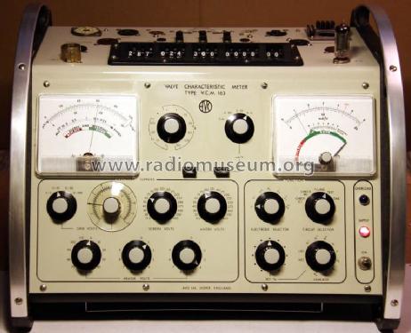
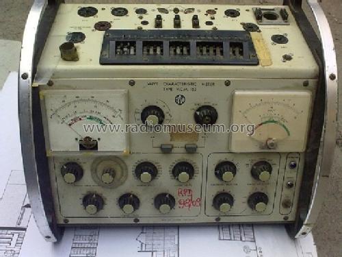
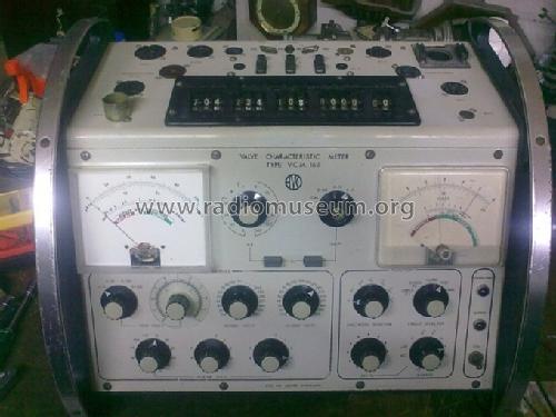
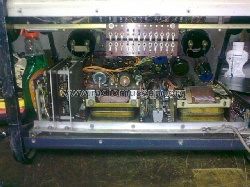
The AVO VCM 163 is one of the few tube testers (British: valve tester) being able to measure tube electrode currents, e.g. plate and screen current (fig. 1, left-hand meter movement) as well as mutual conductance (fig. 1, right-hand meter movement) simultaneously. The VCM 163 is the latest and most elaborate tube tester ever built by AVO.
Figure 1: The AVO Valve Characteristic Meter V.C.M. 163
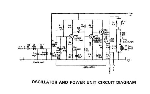
All voltages applied to the electron tube under test are pure 50 Hz line frequency sine waves. The plate (British: anode) as well as the screen electrode via diodes D1 and D2 are supplied with sinusoidal positive half wave voltages (cf. fig. 2). AVO unusually terms rectifier diodes D1 and D2 ‘suppressor’ diodes probably due to the fact that they suppress the negative half wave. Via diode D4 an unsmoothed negative half wave (grid BIAS) is applied to the grid electrode in proper phase relationship, i.e. anti-phase, to the positive electrode voltages. This is quite a clever and economical principle because the power supply becomes extremely simple (among other things no filtering). In addition power requirement of the line transformer (C core type) is half compared to a DC supply.
A) Principle of measurement of plate and screen current
AVO engineers have evaluated and verified that if alternating electrode voltages are applied in their correct proportions an amplifying tube (by virtue of its property of self-rectification) produces DC plate and screen currents, which for all practical purposes, bear an almost constant relationship to those obtained from its DC static characteristics. In the VCM 163 the following relationship between AC supply and DC static characteristics is implemented:
The left meter movement (cf. fig. 1) reads DC plate and screen current continuously. As a further consequence of the fictive static characteristic of the VCM 163 test conditions of a tube can be directly obtained from the tube manufacturers published curves or data.
B) Principle of mutual conductance measurement
Measurement of mutual conductance (= transconductance) is based on a sophisticated operational principle using a transistorized high frequency (HF) oscillator and a frequency selective HF amplifier (fig. 2, High Pass Filter & Amplifier). The grid BIAS signal and the HF signal are added and routed to the grid of the test tube. Detailed schematics are shown in figs 7 & 8.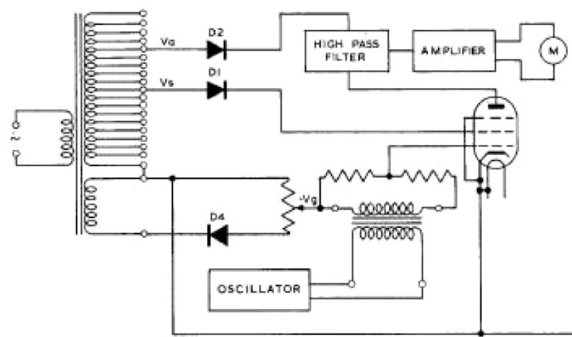
Figure 2: Basic circuit for mutual conductance measurement
(Source: Operational Manual)
Below, a few voltage measurements performed to clarify the principle of mutual conductance measurement as used in this premium instrument developed by AVO are presented.
The amplitude of the negative 50 Hz grid BIAS voltage can be selected in four ranges from 0-100 Volt. This BIAS voltage is superimposed by a low voltage grid HF signal the amplitude of which is well stabilized. HF modulation of the grid voltage results in a proportional plate HF current. Mutual conductance is derived from the band-pass filtered plate HF current set into relation to the applied grid HF signal amplitude.
The following voltage measurements were registered using a Tektronix TDS 210 oscilloscope. There was no test tube inserted into the VCM 163.
Due to the fact that the high frequency grid signal is magnitudes smaller than the Ugrid BIAS amplitude the superimposed grid signal is not readily visible (figure 3).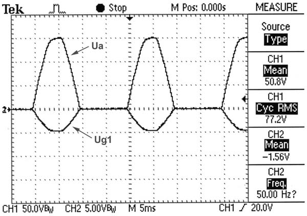
Figure 3: Simultaneous display of Uplate and Ugrid (50 Hz frequency)
Channel 1: positive half wave plate voltage (Uplate) at 50V/div
Channel 2: negative half wave grid voltage (Ugrid) at 5V/div
To visualize the grid HF signal ‘riding’ on the 50 Hz grid BIAS supply amplification was increased from 5 Volt to 0.2 Volt per division.
Figure 4: Ugrid at higher amplification (200mV/div)
Especially in the horizontal parts of Ugrid recording the superimposed HF grid signal now becomes noticeable as wide traces (fig. 4, arrow). For further clarification of the combined signal to the grid figure 5 illustrates the grid HF signal component using higher amplification (20mV/div) and faster time deflection (50µs/div).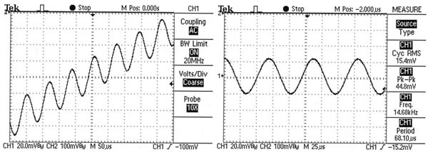
Figure 5: Grid signal (Range 0-6 mA/V)
Left insert: Grid HF signal at the rising part of the 50Hz BIAS sine wave
Right insert: Grid HF signal at zero BIAS voltage
Frequency of the grid HF signal (not mentioned in any AVO manual) was found to be 14.68 kHz.
The AVO VCM 163 offers three selectable ranges for mutual conductance measurement by switching the amplitude of the grid HF signal.
Figure 6: Grid HF signals at 3 selectable mutual conductance ranges
Voltages shown in the MEASURE panel (right-hand side) correspond
to the 0-6 mA/V range
Tubes with low mutual conductance (0-6 mA/V) are measured using a large amplitude grid HF signal whereas tubes with high (0-20 mA/V) or very high mutual conductance (0-60 mA/V) require lower signal amplitudes.
As a general purpose tube tester the VCM 163 in addition to the above described features is able to:
• check the heater continuity
• measure insulation between electrodes with the tube either being cold or hot
• check rectifiers and diodes under load conditions
• measure gas current up to 100 µA f.s.d.
A remarkable highlight of the mechanical sturdy construction of the instrument is the use of a huge thumbwheel switch 13 pin electrode selector (cf. fig. 1).
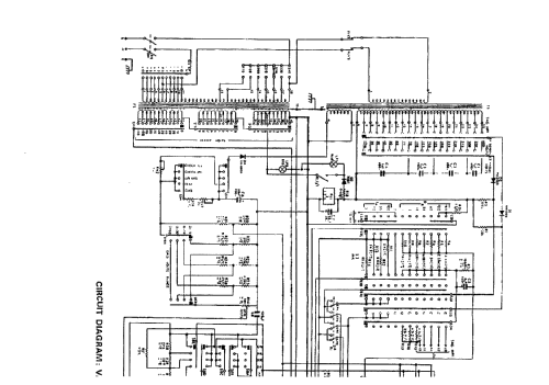
Figure 7: Circuit diagram of the AVO VCM 163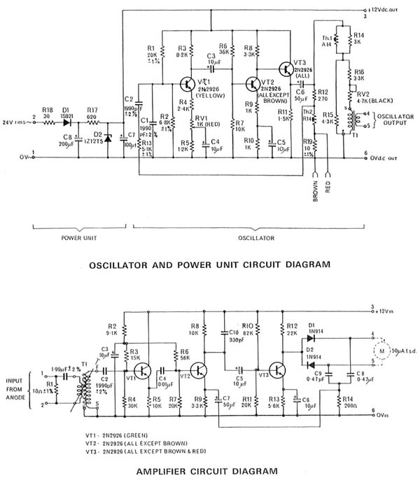
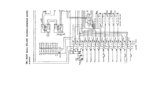
Figure 8: Circuit diagrams of the transistorized modules (shown as block diagrams in fig. 7)
Kurt Schmid, 23.Mar.12
Hello, I have a simple question. Hopefully someone can answer. I am looking for the machine screw thread size, that is used on the bulk of the small machine screws that secure the various panels, (back , sides, front, etc). I am wondering if is a currently available, or a now obsolete size. As close as I can tell it is the roughly about 6/32", only it has more threads per inch. I have a 3.5 mm set screw that will go in part way, and then stop. The 3.5mm set screw seems to have more threads per inch than the screws used in this tester. I am only asking because the unit I came across is missing a few, and i would like to make it complete. I'm thinking they might be metric, but are they an obsolete imperial size ? I thought it might be listed in the manual, but the screws are not.
While I am asking, they also used 8 rubber isolation (damper) grommets on the large bolts that secure the corners of this tester. Mine seem to be hard and crumbling, (literally falling apart). I know it isn't a real critical area. Would someone know what size to use as replacements, or just something that is "close enough' as far as rubber grommets go?
Thank-you to all in advance. Tony
Tony Fulford, 12.Feb.22