- Produttore / Marca
- Browning-Drake Corp.; Brighton, Massachusetts
- Anno
- 1928
- Categoria
- Kit, scatola di montaggio (parti sfuse e istruzioni o solo istruzioni di montaggio)
- Radiomuseum.org ID
- 34644
- Principio generale
- A circuiti accordati (TRF o amplif. diretta in generale); A valvole con griglia schermo (solo se 1926-1935)
- Tensioni di funzionamento
- Alimentazione a corrente alternata (CA)
- Materiali
- Vari materiali
- Radiomuseum.org
- Modello: Kit - Browning-Drake Corp.; Brighton
- Annotazioni
- One dial (primary tuning control knob)
- Prezzo nel primo anno
- 59.00 $
- Fonte esterna dei dati
- Ernst Erb
- Fonte dei dati
- Radio Collector`s Guide 1921-1932
- Altri modelli
-
In questo link sono elencati 46 modelli, di cui 20 con immagini e 14 con schemi.
Elenco delle radio e altri apparecchi della Browning-Drake Corp.; Brighton, Massachusetts
Discussioni nel forum su questo modello: Browning-Drake Corp.: Kit
Argomenti: 1 | Articoli: 4
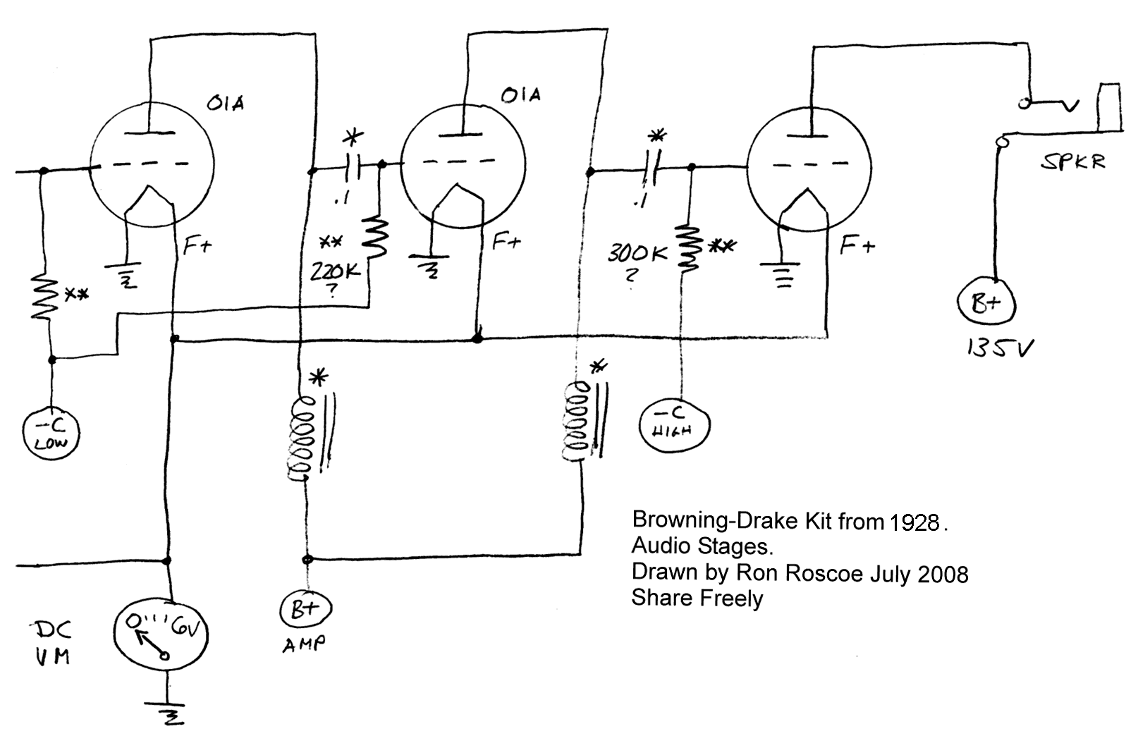
Dear Radiophiles, Ron Roscoe has traced the schematic for his Browning-Drake Kit receiver from 1928.
This receiver employs positive feedback with opposite goals, the first reduces gain from oscillation conditions in the RF stage, while the other increases gain to a point just under oscillation in the regenerative detector:
First, Miller capacitance neutralization is acchieved with positive feedback applied from the secondary of the output RF transformer to the input grid of the RF triode.
Second, Postive feedback current is fed from the plate circuit of the regenerative detector to reinforce the detection efficiency of grid-leak detection. The non-linear detection characteristic of the grid is one of the steps around the positive feedback loop. The positive feedback sharpens the non-linearity of the grid transfer function that is necessary for detection. Much of the sensitivity that a regenerative detector provides comes from the improved detection efficiency, not just the raw increase in overall gain from PFB.
The coils marked "*" at the audio stage plates are integrated with their coupling capacitors marked "*", in National Impedaformers. This one of several coupling schemes that show up in different versions of this kit.
I repaired the National Impedaformer for Ron. I melted out the wax and added a 0.1uf coupling cap, while disconnection one end of the existing cap. The choke was open at it's solder connetions, so it was easy to repair it.
Rivets were drilled out. Heat gun melted out the wax
Just enough heat was used to melt wax. Insulating paper pieces, and integral 0.1uF capacitor.
Grid bias resistor holder visible at the top could be used only for first stage, where zero volts bias was consistent with small audio signals. The wooden coil bobin was removed from the core by twisting the laminations.
Regards,
-Joe
Joe Sousa, 10.Aug.09

