Receiver for High-Definition Signals
BTS (B.T.S.) British Television Supplies; London
- Country
- Great Britain (UK)
- Manufacturer / Brand
- BTS (B.T.S.) British Television Supplies; London
- Year
- 1935 ?
- Category
- Kit (Parts plus instruction) or building instructions only
- Radiomuseum.org ID
- 361613
- Number of Tubes
- 7
- Main principle
- Superhet with RF-stage
- Wave bands
- Short Wave (SW only)
- Power type and voltage
- Alternating Current supply (AC)
- Material
- Metal case, TUBES VISIBLE
- from Radiomuseum.org
- Model: Receiver for High-Definition Signals - BTS B.T.S. British Television
- Shape
- Miscellaneous shapes - described under notes.
- Notes
-
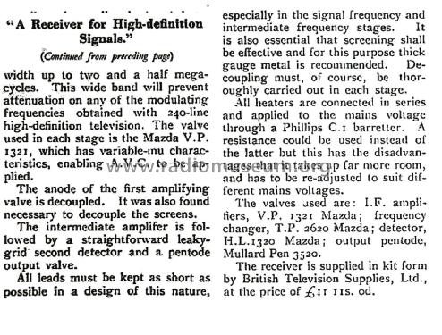
The B.T.S. ultrashort wave receiver was engineered for high-definition television reception, covering a wide wavelength range from 5 to 80 metres (roughly 3.75–60 MHz). Its design prioritised minimal signal loss and maximum bandwidth, making it suitable for the demanding requirements of early television signals.
Key Features and Design Highlights
- Frequency Coverage: 5–80 metres (3.75–60 MHz), encompassing the upper bands where early UK television broadcasts (such as BBC, Baird, and Marconi-EMI systems) operated.
- Circuit Design: The receiver consists of:
- One signal frequency amplifier (grid-tuned, loosely coupled to the aerial)
- Frequency changer (cathode injection)
- Two intermediate frequency (I.F.) stages (tuned to 12 MHz with variable coupling for bandwidth up to 2.5 MHz)
- Second detector (leaky-grid)
- Pentode output stage
- Valves Used:
- IF amplifiers: Mazda V.P. 1321 (variable-mu, enabling automatic volume control)
- Frequency changer: Mazda T.P. 2620 (pentode and triode in one envelope, screened from each other)
- Detector: Mazda H.L. 1320
- Output pentode: Mullard Pen 3520
- Special Materials: Use of Megacite (low-loss, high power factor material) and silver-plated metal parts to reduce losses and improve performance.
- Construction: All leads kept as short as possible, especially in high-frequency stages; effective screening with thick-gauge metal; thorough decoupling in each stage.
- Power Supply: Universal AC/DC valves; heaters connected in series, powered via mains using a Phillips C1 barretter for voltage stabilisation.
- Performance: 2.5 MHz bandwidth to prevent attenuation of high-definition television signals (up to 240-line resolution at the time).
- Application: Designed for high-definition television reception, but also suitable for other ultrashort wave signals. The receiver could be used with mechanical (Nipkow disc) like the BTS Indirect Drive Disc Television Kit display, but by the mid-1930s, all-electronic (cathode ray tube) systems were becoming standard.
Context
The receiver was capable of picking up the UK’s pioneering television broadcasts, which operated at frequencies such as 45 MHz (vision) and 41.5 MHz (sound)—well within the upper part of its coverage. Its advanced design and materials made it a notable example of early television receiver technology, supplied in kit form by British Television Supplies, Ltd., for £11 11s 0d.Note on Display Compatibility
While the receiver could be used with a Nipkow disc display, if the signal format and synchronisation matched, by the mid-1930s, all-electronic display systems using cathode ray tubes were rapidly replacing mechanical displays for television.
- Price in first year of sale
- 11.55 GB £
- Mentioned in
- -- Original prospect or advert (Television & Short Wave World Dec 1935, Page 735)
- Author
- Model page created by Gary Cowans. See "Data change" for further contributors.
- Other Models
-
Here you find 14 models, 8 with images and 0 with schematics for wireless sets etc. In French: TSF for Télégraphie sans fil.
All listed radios etc. from BTS (B.T.S.) British Television Supplies; London

