Jove Receiving Transformer List No. 8834
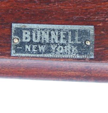
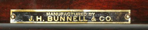
Bunnell & Co., J.H.; Kings Park, NY
- Pays
- Etats-Unis
- Fabricant / Marque
- Bunnell & Co., J.H.; Kings Park, NY
- Année
- 1919
- Catégorie
- Module radio avant 1926 (pas un composant ni clavier)
- Radiomuseum.org ID
- 196992


Bunnell Catalog 41 Dated Nov. 1st, 1919
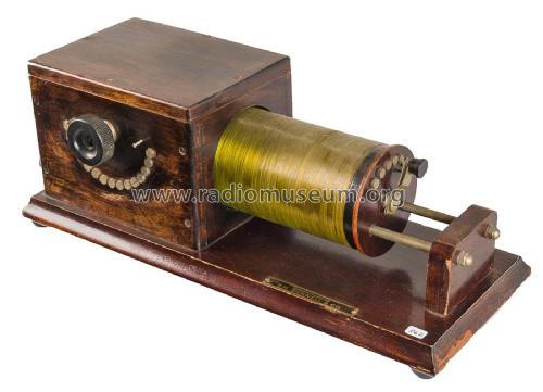


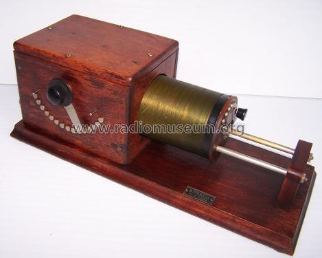
Bunnell Jove Receiving Transformer

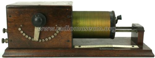
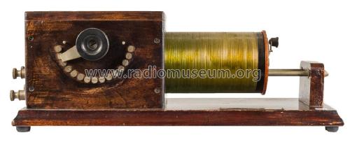
Bunnell Jove Receiving Transformer

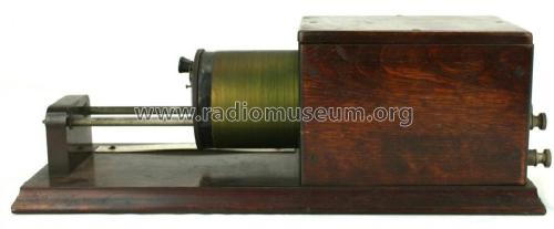
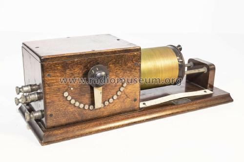
Bunnell Jove Receiving Transformer

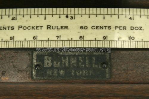
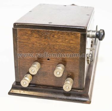
Bunnell Jove Receiving Transformer
Cliquez sur la vignette du schéma pour le demander en tant que document gratuit.
- Principe général
- Circuit d'accord d'avant 1926 (pas de circuits bouchon)
- Gammes d'ondes
- PO et GO
- Tension / type courant
- Pas d'alimentation nécessaire
- Haut-parleur
- - - Pas de sortie basse fréquence
- Matière
- Boitier en bois
- De Radiomuseum.org
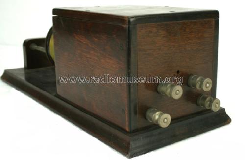
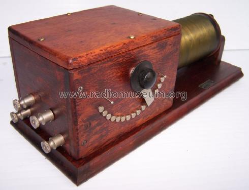
- Modèle: Jove Receiving Transformer List No. 8834 - Bunnell & Co., J.H.; Kings
- Forme
- Modèle de table générique
- Dimensions (LHP)
- 360 x 130 x 140 mm / 14.2 x 5.1 x 5.5 inch
- Remarques
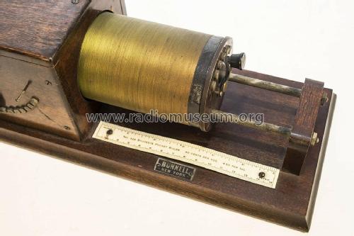
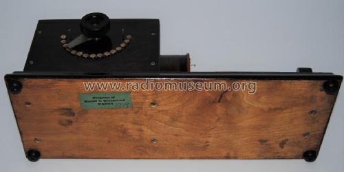
- Nov. 1st 1919 Wireless Catalog for the Bunnell Company. The Jove Receiving Transformer for wave lengths up to 1,800 meters. 15 primary and 6 secondary taps.
- Poids net
- 6 lb (6 lb 0 oz) / 2.724 kg
- Prix de mise sur le marché
- 14.00 $
- Source
- - - Manufacturers Literature
- Schémathèque (1)
- Bunnell Catalog No. 41 Nov. 1st, 1919
- Auteur
- Modèle crée par Alan Larsen. Voir les propositions de modification pour les contributeurs supplémentaires.
- D'autres Modèles
-
Vous pourrez trouver sous ce lien 39 modèles d'appareils, 38 avec des images et 2 avec des schémas.
Tous les appareils de Bunnell & Co., J.H.; Kings Park, NY
Collections
Le modèle Jove Receiving Transformer fait partie des collections des membres suivants.
Contributions du forum pour ce modèle: Bunnell & Co., J.H.;: Jove Receiving Transformer List No. 8834
Discussions: 2 | Publications: 4
This paper describes test bench measurements of a crystal radio using this loose coupler
Pièces jointes
Serioja Tatu, 06.Nov.24
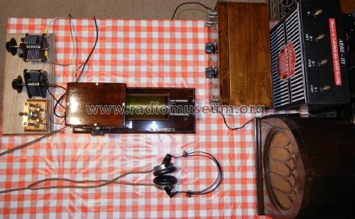
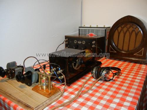
Details of Serioja Tatu's receiver setup:
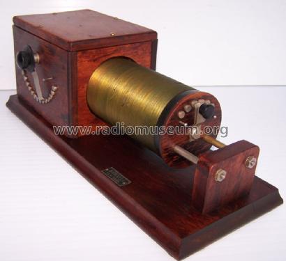
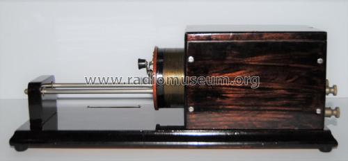
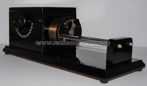
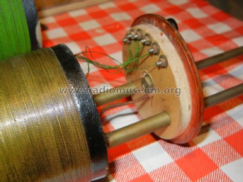
- This is an loose coupler manufactured by the well known J.H. Bunnell & Co. pre 1919. The tuner comes from the Harold Greenwood wireless radio collection. Its paper Greenwood tag is undamaged and affixed to the underside of the base.
- The crystal receiver that use this coupler (see schematic) tunes from 600 KHz to 1410 KHz with the indoor 10 ft. antenna and a ground connection. With the moving coil completely outside and higher impedance static coil (left side) and moving coil switch at 0 position (right) the receiver tunes at 600 KHz. When moving sliding coil inside, the tuned frequency increase without touching any switch or variable capacitor. The tuned frequency increase also when the switch of the static coil is moved toward right, decreasing his inductance.
- A vintage “de Forest Crosley” 2 tube amplifier (2 x 201A tubes) is used on the test bench, in addition to high impedance (2000 ohms) headphones, as seen in related photos.
- Measurements with a Rohde & Schwarz SM300 signal generator with the corresponding adapter for the impedance of a long wire antenna, shows a sensibility of around – 35 dBm over the AM band, with a decent signal to noise ratio in the headphones when the “de Forest Crosley” 2 tube amplifier is used.
Jerry Elarton, 12.Oct.24