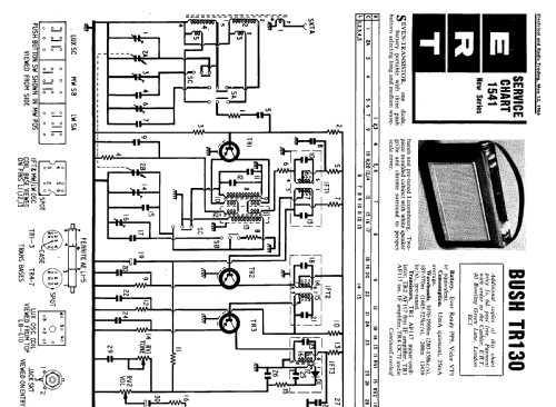
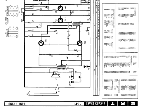
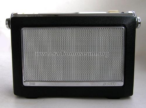
TR130
Bush Radio Ltd.; london
- Country
- Great Britain (UK)
- Manufacturer / Brand
- Bush Radio Ltd.; london
- Year
- 1965
- Category
- Broadcast Receiver - or past WW2 Tuner
- Radiomuseum.org ID
- 72717
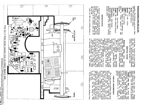


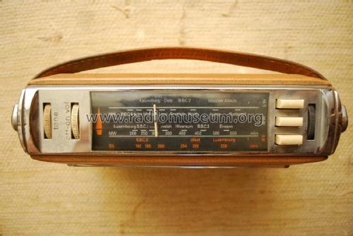
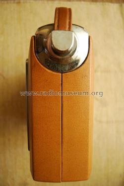


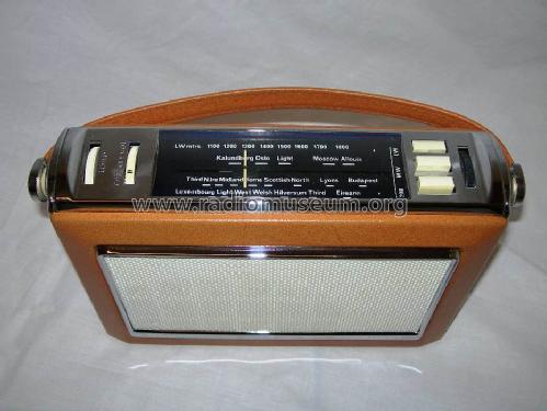
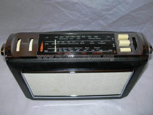
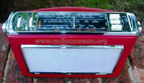
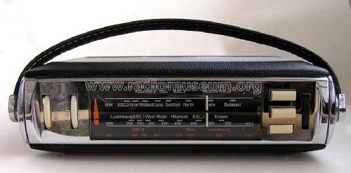
3rd button marked "208"

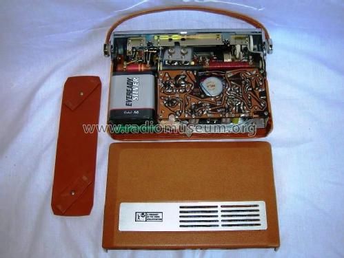
Before restoration/repair ...
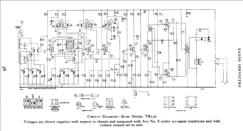
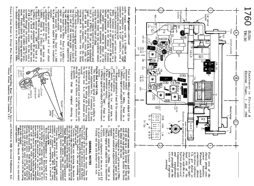
Click on the schematic thumbnail to request the schematic as a free document.
- Number of Transistors
- 7
- Main principle
- Superheterodyne (common); ZF/IF 470 kHz
- Tuned circuits
- 7 AM circuit(s)
- Wave bands
- Broadcast (MW) and Long Wave.
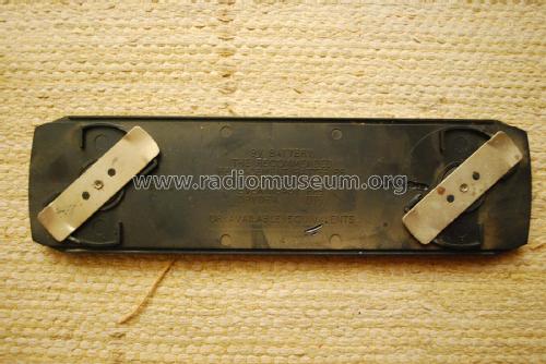
- Power type and voltage
- Dry Batteries / 9 Volt
- Loudspeaker
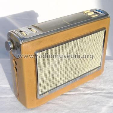
- Permanent Magnet Dynamic (PDyn) Loudspeaker (moving coil) - elliptical
- Power out
- 1 W (unknown quality)
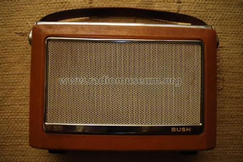
- Material
- Plastics (no bakelite or catalin)
- from Radiomuseum.org
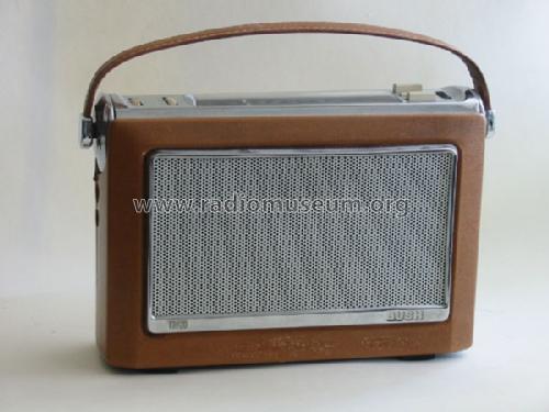
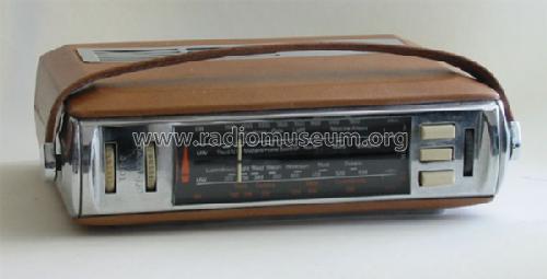
- Model: TR130 - Bush Radio Ltd.; london
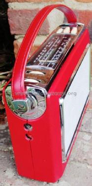
- Shape
- Portable set > 8 inch (also usable without mains)
- Dimensions (WHD)
- 235 x 160 x 73 mm / 9.3 x 6.3 x 2.9 inch
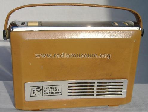
- Notes
- Early models had Radio Luxembourg 208 metres MW pre-set. Sets from mid 1966 onwards had Bandspread 192-208 metres MW.
- Net weight (2.2 lb = 1 kg)
- 2.1 kg / 4 lb 10 oz (4.626 lb)
- Price in first year of sale
- 16.00 GBP
- Author
- Model page created by Egon Penker. See "Data change" for further contributors.
- Other Models
-
Here you find 402 models, 336 with images and 239 with schematics for wireless sets etc. In French: TSF for Télégraphie sans fil.
All listed radios etc. from Bush Radio Ltd.; london
Collections
The model is part of the collections of the following members.
Forum contributions about this model: Bush Radio Ltd.;: TR130
Threads: 1 | Posts: 3
This set had a wire off and Howard Craven kindly emailled me a photo of the location. But it was still dead. The RF/IF section HT rail was only about 4.5V with an 8.4V battery pack. Should be about 7.2V with a fresh battery.
Sticking an audio Tone on the final IF out (the diode is inside the can) gave a tone on the loudspeaker controlled by volume. The Diode tested OK.
I examined the IF to see if it would work with PNP Silicon without Modification. I have BC557 and 2N3906 (not hugely different) general purpose small signal.

I also looked at gain curves for the BC557. They are fairly flat from 0.1mA to 7ma and then drop. No doubt at some lower current the gain drops again.
TR3 is biased by R10 & R12 but has an emitter resistor. I concluded the Silicon part vs Germanium would be between 0.2mA and 0.7mA collector current depending on gain. So no change of resistors needed.
In practice it's power stages and particularly Totem pole Push Pull that are really only very sensitive to bais if you are replacing a low gain Germainium part (Vbe = 0.155V) with a high gain Silicon part (Vbe = 0.63)
The TR2 is trickier as it's AGC. The bais point when there is no signal is potential divider of R7 120K and R11 in series RV2, 18K + 5K = 23K. As the signal level rises the positive voltage from diode reduces the bias (PNP so opposite of Tube AGC) and the Transistor Ic eventually gets low enough that the gain drops. So ironically it's not a higher voltage (0.45V more for Silicon than Germanium) but the initial IC may be too high! A rough calculation suggests that due to the negative feedback at DC of the 680 Ohms R9 and the higher gain that the Collector current may be 0.2mA to 0.45mA At least twice the 0.1mA that is still "full gain".
On both IF stages we are not concerned with Load lines or having the collector at roughly 1/2 HT. It's a low level stage loaded by a transformer. So exact DC point isn't important.
Still dead after replacing TR2 and TR3. But IF injection now gives a tone. But not very loud.
Replaced the last AF117 with a BC557 and HT rose more to 5.6V rather than the orginal 4.5V. RF tone can now be injected. But very low output. RF/IF HT rail only 5.6V. C27 and R25 checked. Leakage high on C27 and R25 is nearly 550 Ohms instead of 470. Replaced 100uF with a 220uF the same size and replaced 470 Ohm. HT on RF/IF section now 7V roughly.
I stuck the 100uF cap on my PSU and wound up the voltage to 25V gradually. The current was initially about 20mA and then dropped to zero.
Discharged and checked: Measures 115uF. So I stuck it back in. With 8.3V battery that RF/IF HT rail was the same 7.05V now with new 200uF or the old 100uF "reformed".
Still nearly non-existant output. AC level and DC level vs generator level is fine on the detector output, so LO and IF all working fine. Good loud tone driving base of TR5. So suspect TR4 OC71 and replace with a BC557. Signal rises a little, but still massive attenuation at the base TR4. Suspect C30 8uF between volume control wiper and series base resistor. It's measuring only a few nF! Replace with 10uF and radio bursts to life. Stick back OC71 and it's just as good.
I confess I bought this set very cheap to use the case, tuning and chassis for a project. But now I have fixed it :-(
Sensitivity is very good on MW and it sounds far better than the Fidelity RAD23 or Sony ICF2001D on RTE1 LW (252kHz).
Would you replace faulty Wax paper capacitors with NOS wax paper or with new Plastic or Ceramic dielectric part? Some AF117 are fine, but many grow whiskers and any "treatment" may not last. So is it terrible to put in some new PNP Silicon when no component changes are needed? When there is an emitter resistor, small signal stage and the Silicon part is much higher gain it's unlikely any bias resistor change is needed.
Michael Watterson, 16.Mar.12