Capehart 1006-M Ch= C-287
Farnsworth Television & Radio Corp. - see also Capehart
- País
- Estados Unidos
- Fabricante / Marca
- Farnsworth Television & Radio Corp. - see also Capehart
- Año
- 1950/1951
- Categoría
- Radio - o Sintonizador pasado WW2
- Radiomuseum.org ID
- 35055
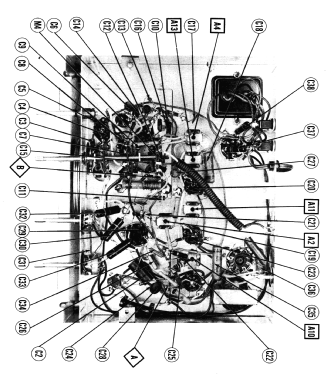


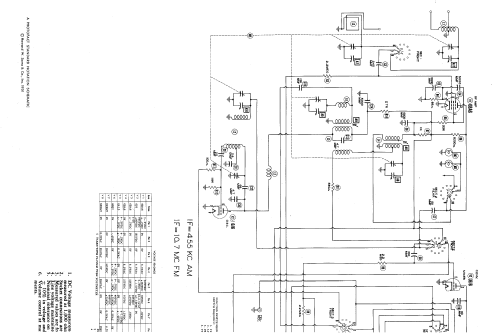


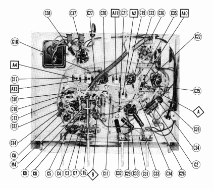
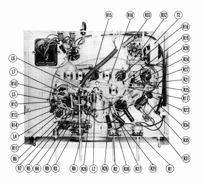


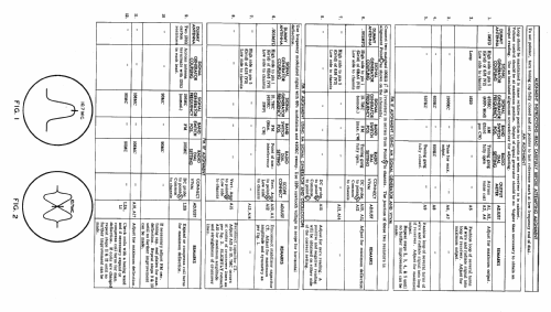
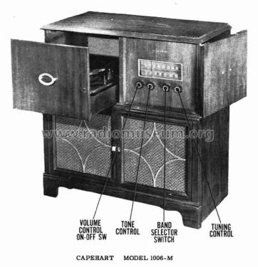
Picture from service manual.

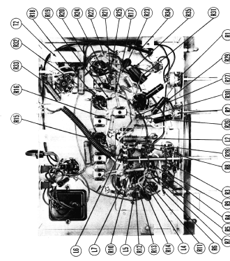
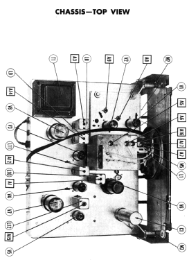
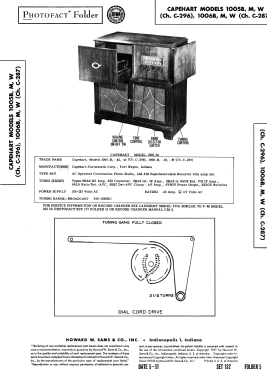
SAMS Photofact for model 1006-M
Haga clic en la miniatura esquemática para solicitarlo como documento gratuito.
- Numero de valvulas
- 8
- Principio principal
- Superheterodino con paso previo de RF; ZF/IF 455/10700 kHz
- Número de circuitos sintonía
- 7 Circuíto(s) AM 9 Circuíto(s) FM
- Gama de ondas
- OM y FM
- Especialidades
- Tocadiscos con cambiador autom.
- Tensión de funcionamiento
- Red: Corriente alterna (CA, Inglés = AC) / 60 Hz, 117V = 110 -120 Volt
- Altavoz
- Altavoz dinámico (de imán permanente) / Ø 11.875 inch = 30.2 cm
- Potencia de salida
- 4 W (unknown quality)
- Material
- Madera
- de Radiomuseum.org
- Modelo: Capehart 1006-M Ch= C-287 - Farnsworth Television & Radio
- Forma
- Consola baja, patas más cortas del 50%.
- Anotaciones
-
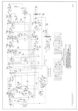
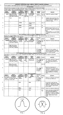
Capehart model 1006M is an AC operated combination phono-radio, AM-FM superheterodyne receiver with loop antenna. According to SAMS Photofact Date 5-51, set 132, folder 5, the following Capehart models, made by Farnsworth Television and Radio Corp., fort Wayne, Indiana use the chassis C-296: 1005B, 1005M and 1005W. The chassis C-287 (on the same sheet) use the models 1006B, 1006M and 1006W. All models have a built in AM loop antenna. We don't know the difference of the chassis except the dial glass.
- Ext. procedencia de los datos
- Ernst Erb
- Procedencia de los datos
- Collector's Guide to Antique Radios (6th edition)
- Referencia esquema
- Rider's Perpetual, Volume 22, covering 1951
- Documentación / Esquemas (1)
- Photofact Folder, Howard W. SAMS (Date 5-51, set 132, folder 5)
- Otros modelos
-
Donde encontrará 401 modelos, 285 con imágenes y 327 con esquemas.
Ir al listado general de Farnsworth Television & Radio Corp. - see also Capehart