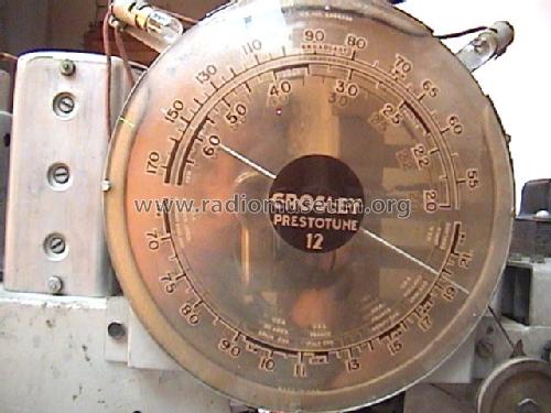
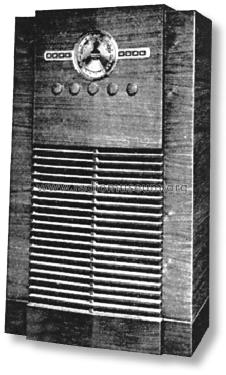
Prestotune 12 Ch= 1217 tall console
Crosley Radio Corp.; Cincinnati (OH)
- Land
- USA
- Hersteller / Marke
- Crosley Radio Corp.; Cincinnati (OH)
- Jahr
- 1937/1938
- Kategorie
- Rundfunkempfänger (Radio - oder Tuner nach WW2)
- Radiomuseum.org ID
- 36195


One of mine, and I'm proud of it :)


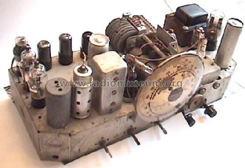

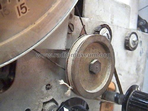
Dial string position detail

Klicken Sie auf den Schaltplanausschnitt, um diesen kostenlos als Dokument anzufordern.
- Anzahl Röhren
- 12
- Hauptprinzip
- Super mit HF-Vorstufe; ZF/IF 455 kHz
- Anzahl Kreise
- 8 Kreis(e) AM
- Wellenbereiche
- Mittelwelle, Kurzwelle und Tropenband.
- Betriebsart / Volt
- Wechselstromspeisung / 110; 220 Volt
- Lautsprecher
- Dynamischer LS, mit Erregerspule (elektrodynamisch)
- Material
- Gerät mit Holzgehäuse
- von Radiomuseum.org
- Modell: Prestotune 12 Ch= 1217 [tall console] - Crosley Radio Corp.;
- Form
- Standgerät mit Drucktasten.
- Abmessungen (BHT)
- 28.7 x 42.7 x 14.5 inch / 729 x 1085 x 368 mm
- Bemerkung
-
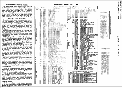
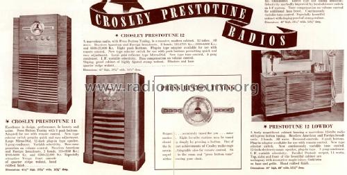
Cabinet 7PF. Pushbutton motor tuning. Wavebands: 535 - 1725 kHz, 2.0 - 6.8 MHz, 6.6 - 22 MHz. Early models had non-locking pushbuttons, later model had locking pushbuttons.
- Nettogewicht
- 31 kg / 68 lb 4.5 oz (68.282 lb)
- Originalpreis
- 138.00 $
- Datenherkunft extern
- Ernst Erb
- Datenherkunft
- Pre-War Consoles
- Schaltungsnachweis
- Rider's Perpetual, Volume 10 = 1939 and before
- Literatur/Schema (3)
- Crosley Folder No. 1918, 1938 for Season 1937/38.
- Weitere Modelle
-
Hier finden Sie 1813 Modelle, davon 1053 mit Bildern und 1306 mit Schaltbildern.
Alle gelisteten Radios usw. von Crosley Radio Corp.; Cincinnati (OH)
Sammlungen
Das Modell Prestotune 12 befindet sich in den Sammlungen folgender Mitglieder.
Forumsbeiträge zum Modell: Crosley Radio Corp.;: Prestotune 12 Ch= 1217
Threads: 4 | Posts: 33
Hello dear Radio Collectors. I have decided to make little station labels to go on the eight preset buttons of this radio. Check out my first try at this:

I have two questions:
1. Does anyone know what AM stations might have been on the air in the New York region when this radio was new (1937)? I prefer having historical names to just using whatever local stations I can receive today.
2. I have created a template that fits these buttons. It is in CorelDraw (.cdr) format. Using this, it is very easy to type in any station call letters and print them in the correct size. Do we, in RMorg, have any provision for uploading this type of file and keeping it associated with the model?
Thanks!
Michele Denber, 14.Mar.09
Thanks to everyone for their help with this radio. I ended up replacing all of the electrolytic and paper capacitors. That fixed the excessive current draw but there was still no output. I then replaced the audio amplifier tube which restored normal operation. The radio now works and sounds great. Except for one problem: occasionally, at some random times, the volume will suddenly drop almost in half. Then it will play that way for a while and then it will pop back up to the original level. That cycle continues to go on as long as it's on. What on earth could be causing this? It's hard to trace, because most of the time it is working OK. I have checked all of the tube connections and switch contacts. They seem to be OK. I'm not sure where to begin and would appreciate any advice. Thanks und danke schoen.
- Michele
Michele Denber, 13.Jan.09
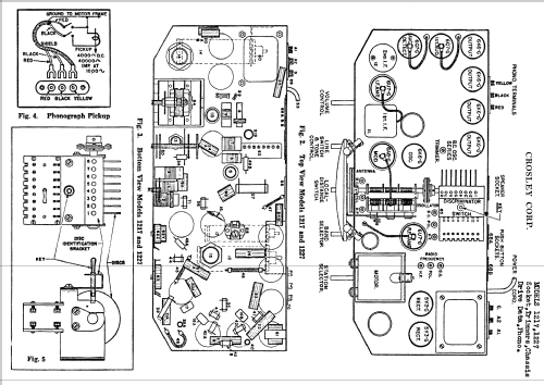
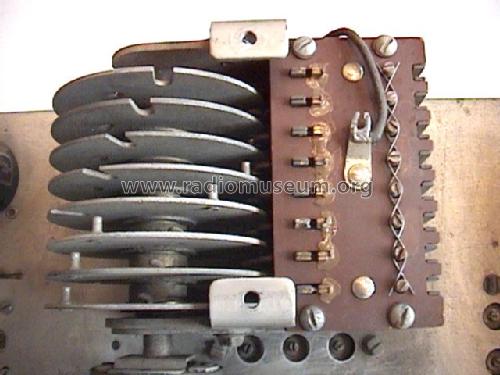
OK, I have another question now. I'm not at all familiar with these old style molded capacitors. The capacitor on the left in mounted upside down, so it reads black-brown-red (you can see the arrows indicating this). The other one is black-green red.
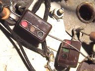
Now, what are the values? According to a table I found on the web, the black-brown-red should be 0-1-00, or 100, and the other one is 500. But what are the units? Is this 100 and 500 uF, nF, or pF?
Also, does anyone have an opinion on the reliability of these components? If they read OK, should I just leave them alone? Are they more reliable than paper capacitors? Any help would be most appreciated. Thanks!
Michele Denber, 18.Dec.08
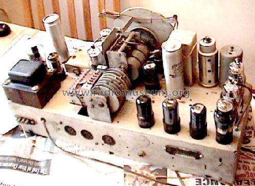
Hello dear collectors. I am restoring a Crosley Prestotune 12 (ch. 1217). While replacing capacitors, I came across C16, a 40 uF can which sits behind the 1st IF can and just to the left of the 6K6 oscillator. I found that it had already been snipped out of the circuit, so I don't know where the wires originally went (see circled part below):

Now here's the mystery. If you look at C16 (circled in red below) and trace its connections in both directions (yellow traces), you see that neither end is directly grounded. And yet my actual component has only one solder connector on it (ground being through the can to the chassis).

So I have a C16 that has to have one end grounded according to the actual radio I'm working on, but neither end is grounded according to the schematic. Is the schematic wrong? Am I wrong? Any ideas? Thanks very much!
Michele Denber, 12.Dec.08