- Produttore / Marca
- Crosley Radio Corp.; Cincinnati (OH)
- Anno
- 1946
- Categoria
- Radio (o sintonizzatore del dopoguerra WW2)
- Radiomuseum.org ID
- 36761
Clicca sulla miniatura dello schema per richiederlo come documento gratuito.
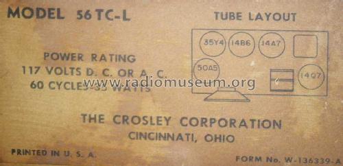
- Numero di tubi
- 5
- Principio generale
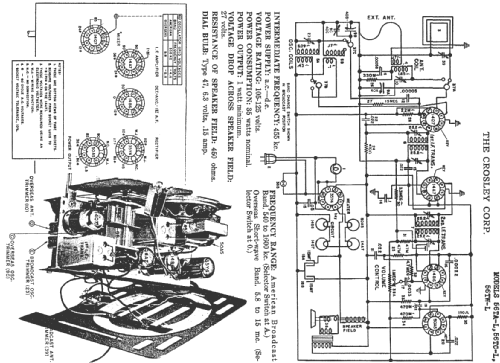
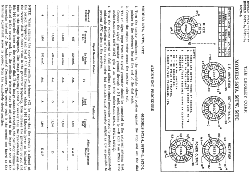
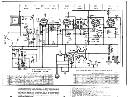
- Supereterodina (in generale); ZF/IF 455 kHz; 2 Stadi BF
- N. di circuiti accordati
- 6 Circuiti Mod. Amp. (AM)
- Gamme d'onda
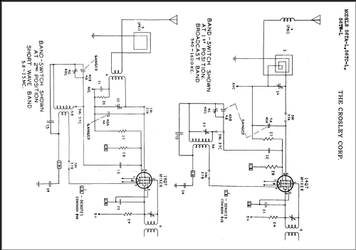
- Onde medie (OM) e corte (OC).
- Tensioni di funzionamento
- Alimentazione universale (doppia: CC/CA) / 105-125 Volt
- Altoparlante
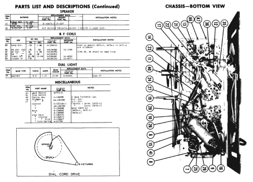
- AP elettrodinamico (bobina mobile e bobina di eccitazione/di campo) / Ø 3.93 inch = 10 cm
- Potenza d'uscita
- 1 W (qualità ignota)
- Materiali
- Mobile in legno
- Radiomuseum.org
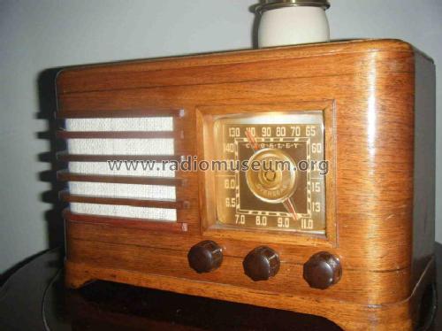
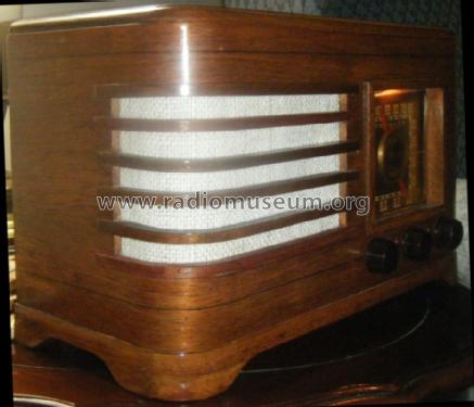
- Modello: 56TC-L - Crosley Radio Corp.;
- Forma
- Soprammobile basso, con andamento orizzontale (grosse dimensioni).
- Annotazioni
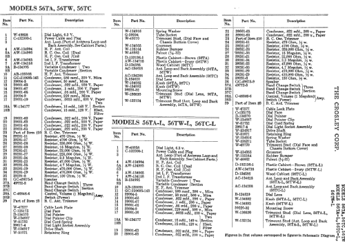
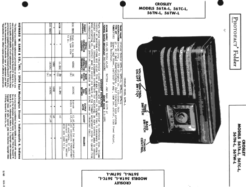
- Same chassis in 56TAL, 56TWL, 56TCL. Sams photofact folder 464-9, date 9-46, features the Crosley models 56TA-L, 56TC-L, 56TN-L and 56TW-L as the same schematic.
- Fonte esterna dei dati
- Ernst Erb
- Fonte dei dati
- Collector's Guide to Antique Radios 4. Edition
- Riferimenti schemi
- Rider's Perpetual, Volume 15 = 1947 and before
- Bibliografia
- Antique Radios, Johnson 1986
- Letteratura / Schemi (1)
- Photofact Folder, Howard W. SAMS (Folder 464-9 date 9-46)
- Altri modelli
-
In questo link sono elencati 1813 modelli, di cui 1053 con immagini e 1306 con schemi.
Elenco delle radio e altri apparecchi della Crosley Radio Corp.; Cincinnati (OH)
Discussioni nel forum su questo modello: Crosley Radio Corp.;: 56TC-L
Argomenti: 1 | Articoli: 3
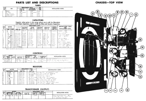
I am currently working on recapping my 56TC-L, while buying my capacitors I ran into a problem. The schematic shows that the radio has a two section 15uF/15uF capacitor, but my actual radio has a three section 20uF/40uF/80uF capacitor. One of the four wires on my three section capacitor has been cut, so I'm assuming that only two of the three sections are connected. So do find a capacitor like mine then use trial and error to find which wire go's unconnected, or do I go with the schematic and find a two section 15uF/15uF capacitor. Please help.
Allegati
- schematic (146 KB)
- three section capacitor (161 KB)
- three section capacitor 2 (154 KB)
Alec Anglum, 25.Jun.13