- Land
- USA
- Hersteller / Marke
- Crosley Radio Corp.; Cincinnati (OH)
- Jahr
- 1946
- Kategorie
- Rundfunkempfänger (Radio - oder Tuner nach WW2)
- Radiomuseum.org ID
- 36761
Klicken Sie auf den Schaltplanausschnitt, um diesen kostenlos als Dokument anzufordern.
- Anzahl Röhren
- 5
- Hauptprinzip
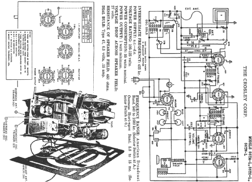
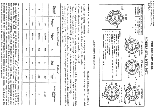
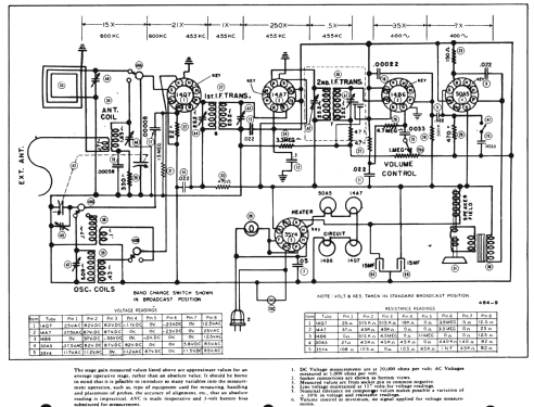
- Superhet allgemein; ZF/IF 455 kHz; 2 NF-Stufe(n)
- Anzahl Kreise
- 6 Kreis(e) AM
- Wellenbereiche
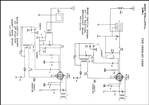
- Mittelwelle und Kurzwelle.
- Betriebsart / Volt
- Allstromgerät / 105-125 Volt
- Lautsprecher
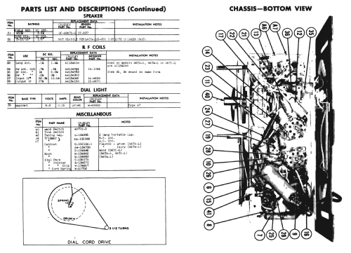
- Dynamischer LS, mit Erregerspule (elektrodynamisch) / Ø 3.93 inch = 10 cm
- Belastbarkeit / Leistung
- 1 W (Qualität unbekannt)
- Material
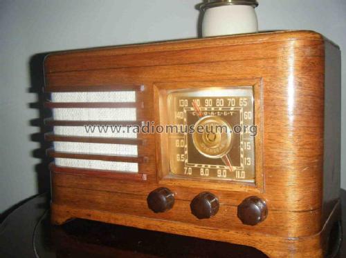
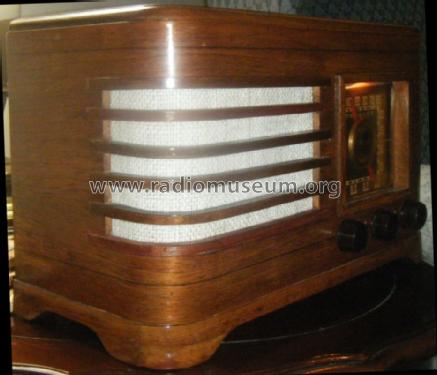
- Gerät mit Holzgehäuse
- von Radiomuseum.org
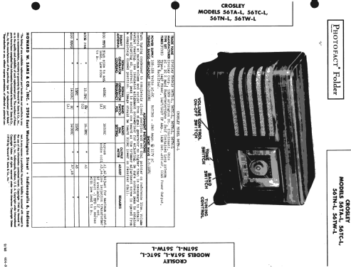
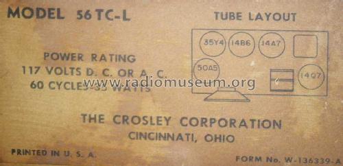
- Modell: 56TC-L - Crosley Radio Corp.;
- Form
- Tischgerät-gross, - Querformat (breiter als hoch oder quadratisch).
- Bemerkung
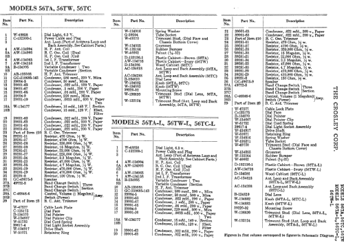
- Same chassis in 56TAL, 56TWL, 56TCL. Sams photofact folder 464-9, date 9-46, features the Crosley models 56TA-L, 56TC-L, 56TN-L and 56TW-L as the same schematic.
- Datenherkunft extern
- Ernst Erb
- Datenherkunft
- Collector's Guide to Antique Radios 4. Edition
- Schaltungsnachweis
- Rider's Perpetual, Volume 15 = 1947 and before
- Literaturnachweis
- Antique Radios, Johnson 1986
- Literatur/Schema (1)
- Photofact Folder, Howard W. SAMS (Folder 464-9 date 9-46)
- Weitere Modelle
-
Hier finden Sie 1812 Modelle, davon 1050 mit Bildern und 1306 mit Schaltbildern.
Alle gelisteten Radios usw. von Crosley Radio Corp.; Cincinnati (OH)
Sammlungen
Das Modell 56TC-L befindet sich in den Sammlungen folgender Mitglieder.
Forumsbeiträge zum Modell: Crosley Radio Corp.;: 56TC-L
Threads: 1 | Posts: 3
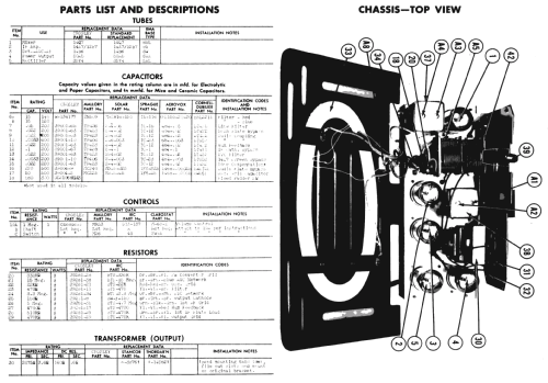
I am currently working on recapping my 56TC-L, while buying my capacitors I ran into a problem. The schematic shows that the radio has a two section 15uF/15uF capacitor, but my actual radio has a three section 20uF/40uF/80uF capacitor. One of the four wires on my three section capacitor has been cut, so I'm assuming that only two of the three sections are connected. So do find a capacitor like mine then use trial and error to find which wire go's unconnected, or do I go with the schematic and find a two section 15uF/15uF capacitor. Please help.
Anlagen
- schematic (146 KB)
- three section capacitor (161 KB)
- three section capacitor 2 (154 KB)
Alec Anglum, 25.Jun.13