Marine radar Type 12
Decca Radar Ltd.; Surrey
- País
- Gran Bretaña (GB)
- Fabricante / Marca
- Decca Radar Ltd.; Surrey
- Año
- 1951
- Categoría
- RADAR equipment
- Radiomuseum.org ID
- 303934


Manufacturer's documentation

Manufacturer's documentation
Manufacturer's documentation
Manufacturer's documentation
Manufacturer's documentation

Manufacturer's documentation
Manufacturer's documentation
Haga clic en la miniatura esquemática para solicitarlo como documento gratuito.
- Numero de valvulas
- 65
- Válvulas
- M503 723A/B BS52 EF91 ECC91 EB91 19G3 QS150/15 QS95/10 EF55 UU5 11E3 6SN7 EY91 EL38 VR105-30 12TO1A
- Principio principal
- ZF/IF 30,000 kHz
- Gama de ondas
- Bandas de recepción puestas en notas.
- Tensión de funcionamiento
- Alimentado desde otro equipo o aparato principal.
- Material
- Metálico
- de Radiomuseum.org
- Modelo: Marine radar Type 12 - Decca Radar Ltd.; Surrey
- Anotaciones
-
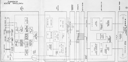
Decca Radar Ltd was founded in 1945 to produce marine radar systems. After extensive sea trials the first product, the Type 159B radar, was launched in 1950 and was an immediate success. The Type 12, which succeeded it in 1951, was designed with a higher specification and a 12" CRT PPI display instead of a 9" one.
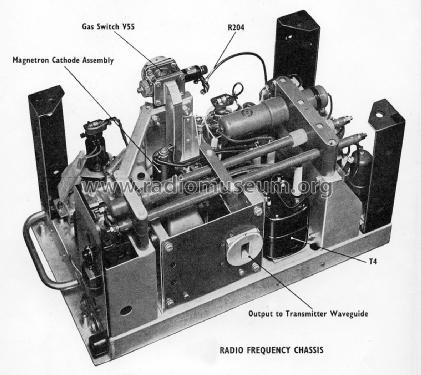
Modulator output to M503 magnetron 5.5 kV 6A pulses.
Peak power output 7 kW.
Frequency 9375 MHz ± 30 MHz.
PRF 1 kHz.
Pulse duration 0.1 or 0.2 µs.
Scanner rotation speed 24 rpm ± 1 rpm.
IF 30 MHz. Flat bandwidth from 25 to 35 MHz.
Maximum gain from input to detector 86 dB.
Max cable length from scanner to receiver unit 220 ft (67 m).
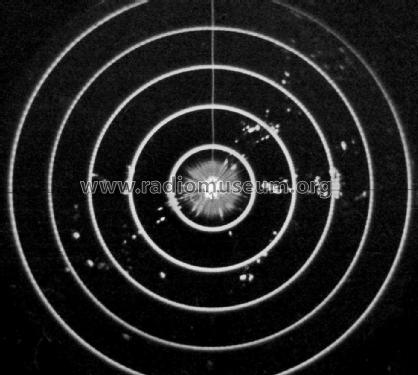
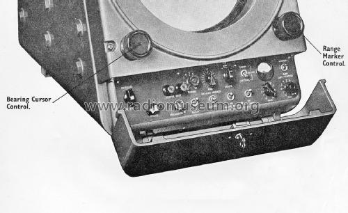
Selectable ranges 1, 10 and 25 nautical miles.
Calibration range rings and heading marker.
Anti sea-clutter, anti rain-clutter, gain and tuning controls.
Provision for an additional remote display unit.
A delay switch prevents the application of EHT for 3 or 4 minutes after power up.Twin parabolic cheese antennas, each 3 in (7.62 cm) high by 4 ft (121.92 cm) wide, fed by double hoghorn assembly located at the focus.
Horizontal beamwidth 1.7 deg, vertical beamwidth 23 deg. Near sidelobes (around 5 deg) at least 23 dB below the main beam; wide angle sidelobes (around 80 deg) 27 dB down.
723A/B reflex klystron local oscillator, tunable over 9375 MHz ± 30 MHz. Output 25 mW, of which about 1 mW is transferred to the main waveguide via a two-hole directional coupler.
CS3A crystal mixer. Current can be monitored at the display.
A BTH BS52 gas TR switch was included in some models to protect the mixer crystal. When present, it is inserted in the receiving waveguide directly after the RF unit input flange.
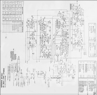
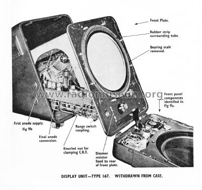
12TO1A CRT with mechanically driven deflection coils synchronised with the scanner. Magnetic focussing.
An azimuth stabiliser driven by a ship's compass repeater can be connected between the bearing transmitter and receiver so that 0 deg on the PPI display indicates north, and the heading marker follows the ship's course.
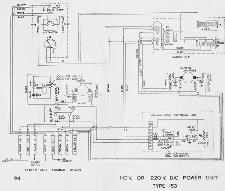
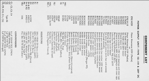
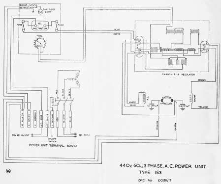
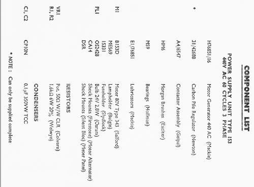
The system is powered by a Mackie Type 'S' 80 V 1000 Hz 500 VA alternator, driven by a 110 or 220 V compound wound DC motor with Creed governor, or by a 440 V 60 Hz 3-phase squirrel-cage induction motor. The scanner drive motors are also selected to correspond with the supply used.
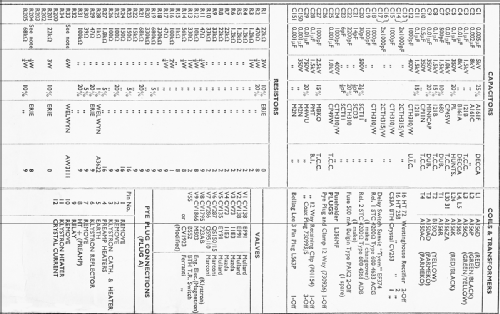
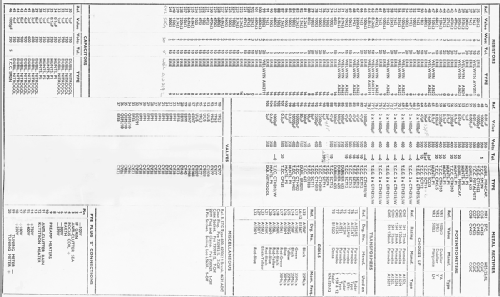
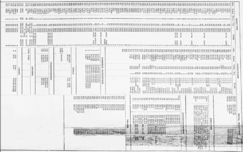
Valve complement:
RF unit (10)
M503 magnetron
723A/B LO klystron
BS52 TR switch
2 EF91
2 11E3
EY91
QS150/15
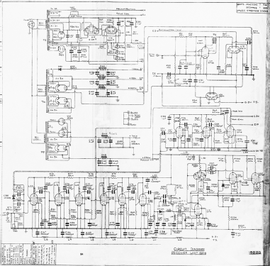
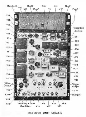
QS95/10Receiver unit (27)
10 EF91
4 19G3
3 UU5
3 EF55
2 6SN7
2 EB91
2 QS95/10
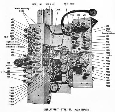
ECC91Display unit (28)
12TO1A CRT
12 ECC91
6 EB91
3 EF91
3 QS150/15
EL38
ECC91
VR105/30
- Autor
- Modelo creado por Bruce Taylor. Ver en "Modificar Ficha" los participantes posteriores.
- Otros modelos
-
Donde encontrará 2 modelos, 2 con imágenes y 1 con esquemas.
Ir al listado general de Decca Radar Ltd.; Surrey
Colecciones
El modelo Marine radar es parte de las colecciones de los siguientes miembros.