AP180 Ch= AP
Emerson Radio & Phonograph Corp.; New York, NY
- Country
- United States of America (USA)
- Manufacturer / Brand
- Emerson Radio & Phonograph Corp.; New York, NY
- Year
- 1937 ?
- Category
- Broadcast Receiver - or past WW2 Tuner
- Radiomuseum.org ID
- 38752
-
- alternative name: Emerson Television
Click on the schematic thumbnail to request the schematic as a free document.
- Number of Tubes
- 5
- Main principle
- Superheterodyne (common); ZF/IF 456 kHz; 2 AF stage(s)
- Tuned circuits
- 6 AM circuit(s)
- Wave bands
- Broadcast, Long Wave and Short Wave.
- Power type and voltage
- AC/DC-set / 105-125 Volt
- Loudspeaker
- Electro Magnetic Dynamic LS (moving-coil with field excitation coil) / Ø 6.5 inch = 16.5 cm
- from Radiomuseum.org
- Model: AP180 Ch= AP - Emerson Radio & Phonograph
- Notes
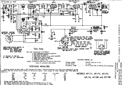
- The Emerson model AP-174 features LW(150-375kHz), BC(540-1600kHz) and SW(5.7-17.5MHz) bands. Uses either 6.5" or 10" speaker. The chassis AP is used for the following models: AP-171, AP-173, AP-174, AP-176, AP-180 and AP-185.
- External source of data
- Ernst Erb
- Circuit diagram reference
- Rider's Perpetual, Volume 8 = 1937 and before
- Other Models
-
Here you find 2098 models, 1152 with images and 1656 with schematics for wireless sets etc. In French: TSF for Télégraphie sans fil.
All listed radios etc. from Emerson Radio & Phonograph Corp.; New York, NY