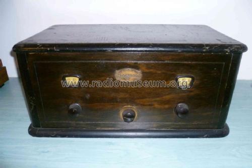
12 table model
Ferguson (in the United States - see text)
- Pays
- Etats-Unis
- Fabricant / Marque
- Ferguson (in the United States - see text)
- Année
- 1926/1927
- Catégorie
- Radio - ou tuner d'après la guerre 1939-45
- Radiomuseum.org ID
- 40495
-
- alternative name: Ferguson Co., J.B. || Ferguson Radio Corp. || Ferguson Radio &Television Co., Inc.

Cliquez sur la vignette du schéma pour le demander en tant que document gratuit.
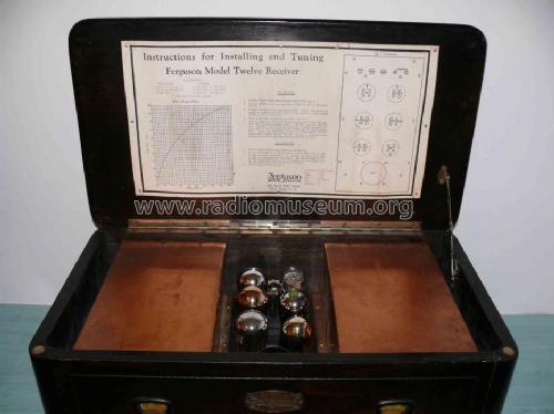
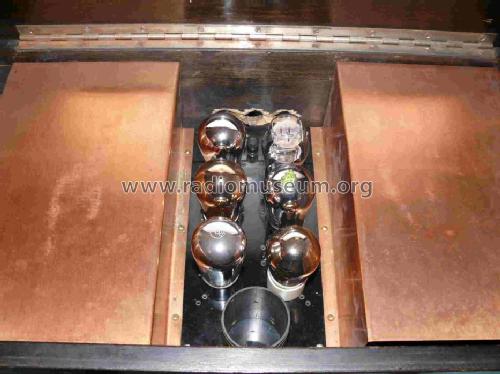
- No. de tubes
- 6
- Lampes / Tubes
- Principe général
- Récepteur TRF en général (avec ou sans réaction inconnu)
- Gammes d'ondes
- PO uniquement
- Tension / type courant
- Piles (rechargeables ou/et sèches)
- Haut-parleur
- - Ce modèle nécessite des HP externes
- Matière
- Boitier en bois
- De Radiomuseum.org
- Modèle: 12 table model - Ferguson in the United States
- Forme
- Modèle de table générique
- Remarques
- Two dials (primary tuning control knobs)
- Prix de mise sur le marché
- 75.00 $
- Source extérieure
- Ernst Erb
- Littérature
- Collector's Guide to Antique Radios 4. Edition
- D'autres Modèles
-
Vous pourrez trouver sous ce lien 66 modèles d'appareils, 16 avec des images et 39 avec des schémas.
Tous les appareils de Ferguson (in the United States - see text)
Contributions du forum pour ce modèle: Ferguson in the: 12 table model
Discussions: 1 | Publications: 3
Hello,
I own a Ferguson - 12, but I do not know if it is the old or the new one. I have unmounted it from the case for drawing schematic and doing some minor repairs.
It has 3 AF stages. The coupling between 1-2 and 2-3 are RC. The coupling between detector and 1st AF is by a transformer of the brand “Silver - Marshall”. Because the shape of transformer mounting and connections I think it could not to be the original.
In addition, I need some information about DC supply:
The are four +B sources ( detector plate, RF , AF(1-2) stages and power stage. May be 22.5 for detector, 135 for power and ¿ what for AF and RF ?
There is -C for grid returns of the 3 AF stages, the same for all three, two of them 201A and the last one of 112A type. For both tubes -C would be -9 volts if +B were 135. But 201A and 112A have a diferent DC wire.
The reostat is only conected to the RF amplifier (2 tubes). Then, all other tubes should work at battery voltage ( 6 or more volts) ?
Finally, I suppose that -B is connected to ground. Ins this case, if +A battery is connected to -B, the grid return of AF would be to +A, not usual, I think. The grid of detector tube returns also to +A, but it is a 200A, and for this also seems to be wrong.
I will be thankful for much any information or suggestion on this subject.
Felix Corrochano, 13.Jan.11