Supradyne à 5 lampes
Gamma, Éts., Georges Gavoret & Cie; Paris, Izieux
- País
- Francia
- Fabricante / Marca
- Gamma, Éts., Georges Gavoret & Cie; Paris, Izieux
- Año
- 1930 ??
- Categoría
- Kit (Partes con instruciones) o Solo Instrucciones
- Radiomuseum.org ID
- 287376
Haga clic en la miniatura esquemática para solicitarlo como documento gratuito.
- Numero de valvulas
- 5
- Principio principal
- Superheterodino en general; ZF/IF 55 kHz; 1 Etapas de AF
- Número de circuitos sintonía
- 3 Circuíto(s) AM
- Gama de ondas
- OM y OL
- Tensión de funcionamiento
- Baterías recargables o pilas / 4 & 40 & 60 & 80 & 120 & negative bias Volt
- Altavoz
- - Este modelo usa altavoz exterior (1 o más).
- Material
- Materiales diversos
- de Radiomuseum.org
- Modelo: Supradyne à 5 lampes - Gamma, Éts., Georges Gavoret &
- Forma
- Chasis (tambien de autoradio)
- Ancho, altura, profundidad
- 360 x 230 x 105 mm / 14.2 x 9.1 x 4.1 inch
- Anotaciones
-
Instructions de montage / kit assembly instructions, "Supradyne Gamma à 5 lampes".
Publié par / published by Ing. I. C. FLOREA, "Toate Tainele Radiofoniei" ("Tous les Secrets de la Radiophonie" / "All the Secrets of Radiophony"), Bucharest 1930.
- Documentación / Esquemas (1)
- Ing. I. C. FLOREA "Toate Tainele Radiofoniei", p.288-290
- Autor
- Modelo creado por Pitagora-Petru Schorsch. Ver en "Modificar Ficha" los participantes posteriores.
- Otros modelos
-
Donde encontrará 18 modelos, 15 con imágenes y 2 con esquemas.
Ir al listado general de Gamma, Éts., Georges Gavoret & Cie; Paris, Izieux
Colecciones
El modelo Supradyne à 5 lampes es parte de las colecciones de los siguientes miembros.
Contribuciones en el Foro acerca de este modelo: Gamma, Éts., Georges: Supradyne à 5 lampes
Hilos: 1 | Mensajes: 1
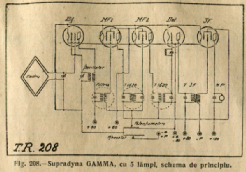
HOW TO ASSEMBLE THE GAMMA “SUPRADYNE” WITH FIVE VALVES
The study of the screen grid valve (§51) emphasized the advantages to be gained by its employment in the intermediate frequency stages. The present set – a very interesting achievement - puts this in practice: Although using before detection two valves with a very high gain, the size of the set is very small, due to a carefully designed screening. The circuit diagram (fig. 208) shows a common frequency-mixer-receiver employing a two-grid valve (bigrille) in the first stage:

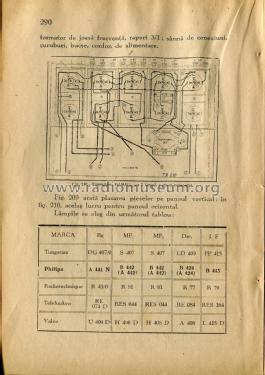
Fig.209 shows the wiring and components on the vertical panel:

Fig. 210 shows the same on the horizontal panel:

The set’s sensitivity reaches the upper limit, due to the employment of the two screen-grid valves as intermediate frequency amplifiers, and especially to the careful screening, allowing maximum amplification without the risk of self-oscillation. Also due to the employment of the screen grid valves, the high selectivity, common to every super-heterodyne, is here sensibly enhanced.
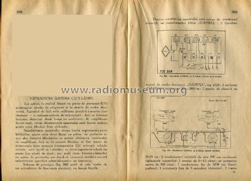
Following parts are needed to assembly the set:
1 "GAMMA" filter transformer.
2 "GAMMA" intermediate frequency transformers, type 1620.
1 "GAMMA" combined oscillator, 200 - 2000 m.
1 ebonite panel 36 × 23 cm.
2 slow-motion 500 cm variable capacitors.
1 rheostat 6 - 10 ohms.
1 potentiometer 400 ohms.
1 fix capacitor 3000 cm (loudspeaker).
1 resistor 3 Megohms (grid leak).
1 low frequency transformer ratio 1: 3.
Connection wire, screws, banana sockets power supply cord.
[The publicity section of the book contains at page 298 an advert from one of the main radio-parts supplier in Bucharest in those times: “RADIO-MATERIAL NICOLAE SARU” offering the complete set of components for the kit:]

The valves could be chosen from the following list:

*****
Anexos
- GAMMA_SUPRADYNE5_HOR (251 KB)
- GAMMA_SUPRADYNE5_QUOTE (239 KB)
- GAMMA_SUPRADYNE5_VALVES (222 KB)
- GAMMA_Supradyne5_sch (210 KB)
- GAMMA_SUPRADYNE5_VERT (251 KB)
Pitagora-Petru Schorsch, 17.Jan.17