Impedance Bridge 1656
General Radio Company; Cambridge (MA)
- Pays
- Etats-Unis
- Fabricant / Marque
- General Radio Company; Cambridge (MA)
- Année
- 1977 ?
- Catégorie
- Appareils de mesure et de dépannage (matériel de labo)
- Radiomuseum.org ID
- 132511
-
- alternative name: GenRad


Cliquez sur la vignette du schéma pour le demander en tant que document gratuit.
- No. de transistors
- 11
- Semi-conducteurs
- Gammes d'ondes
- - sans
- Tension / type courant
- Piles sèches / 5 x 1,5 Volt
- Matière
- Boitier métallique
- De Radiomuseum.org
- Modèle: Impedance Bridge 1656 - General Radio Company;
- Dimensions (LHP)
- 483 x 311 x 146 mm / 19 x 12.2 x 5.7 inch
- Remarques
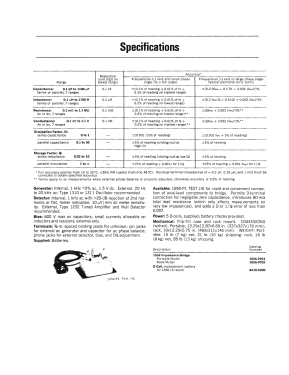
- RLC Messbrücke mit typ. 0,1% Genauigkeit
0,1pF - 1100µF; 0,1µH - 1100H; 0,1mOhm - 1,1MOhm
Güte: D: 0,1 - 50; Q 0,02 - 10.
- Auteur
- Modèle crée par Guido Lindges. Voir les propositions de modification pour les contributeurs supplémentaires.
- D'autres Modèles
-
Vous pourrez trouver sous ce lien 244 modèles d'appareils, 216 avec des images et 131 avec des schémas.
Tous les appareils de General Radio Company; Cambridge (MA)
Collections
Le modèle Impedance Bridge fait partie des collections des membres suivants.
Contributions du forum pour ce modèle: General Radio: Impedance Bridge 1656
Discussions: 1 | Publications: 1
General Radio Company
CONDENSED OPERATING INSTRUCTIONS
Type 1656 Impedance Bridge
Refer to complete instruction manual for details.

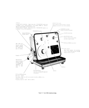
1. BIAS jack.
Voltage bias for capacitors: Apply bias only if PARAMETER switch is in Cs position. For Cp,refer to Section 2. Max voltage is 600 V dc. Add a resistor as a current limiter to prevent short circuit. Current bias for inductors: Apply bias only if PARAMETER switch is in Lp position. For Ls, refer to Section 2.
2. Internal OSCillator LEVEL control.
3. PARAMETER switch.
4. GENERATOR switch.
Turns bridge on, selects internal or external generator, ac or dc, dc zero, checks batteries.
5. UNKNOWN terminals. Connect unknown impedance
6. GUARD connection.
7. MULTIPLIER switch.
Multiply CGRL decade setting by switch range for result.
8. DETector SENSitivity control.
9. CG R L decade:
Main balance control. For greatest accuracy, choose MULTIPLIER setting for balance between 1 and 10.
10. ZERO dc
11. DQ dial.
12. EXTernal DQ jack.
Useful for extending DQ range with a decade box.
13. EXTernal GENerator jack.
Max power: 0.05 W.
Max voltage: 500 V dc; or 5 V ac rms where f is in Hz or 100 V ac rms, whichever is smaller. Frequency range for L and C: 20 Hz to 20 kHz.
14. DETector jack.
Useful to connect external amplifier or earphones for additional sensitivity or selectivity.
15. Ground.
16. OPP ARM jack.
Connect external decade capacitor for reactive balance of resistors.
- a. Turn GENERATOR switch to BAT CHECK1 position. If the meter pointer is not in the BAT sector, replace the batteries in the tube.
- b. Turn GENERATOR switch to AC INTERNAL 1 kHz.
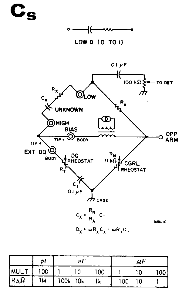
- c. Turn PARAMETER switch to Cs.
- d. Connect the unknown so that most stray capacitance is between the LOW terminal and the case.
- e. Turn OSC LEVEL full cw. The panel control affects only the internal oscillator.
- f. Turn DQ dial full at cw.
- g. Set the CGRL decade near 5000.
- h. Adjust DET SENS for about 6 divisions deflection.
- i. Turn MULTIPLIER switch for minimum meter reading.
- j. Alternately adjust, first the CGRL decade, then the DQ dial for the best null, increasing the DET SENS as needed.
- k. If the DQ dial goes into the uncalibrated portion, the unknown should be measured as Cp.
- I. The series capacitance of the unknown equals the product of the CGRL-decade reading and the MULTIPLIER-switch setting.
- m. The D of the unknown is the reading on the outer scale (Low D) of the DQ dial.
- n. Turn GENERATOR switch to OFF.

- a. Turn GENERATOR switch to BAT CHECK1 position. If the meter pointer is not in the BAT sector, replace the batteries in the tube.
- b. Turn GENERATOR switch to AC INTERNAL 1 kHz.
- c. Turn PARAMETER switch to Cp. (Large electrolytics should be measured at a low frequency (120 Hz) for greater accuracy.
- d. Connect the unknown so that most stray capacitance is between the LOW terminal and the 1656 case
- e. Turn OSC LEVEL clockwise. The panel control affects only the internal oscillator.
- f. Turn DQ full ccw.
- g. Set the CGRL decade near 5000.
- h. Adjust DET SENS for about 6 divisions deflection.
- i. Turn MULTIPLIER switch for minimum meter reading.
- j. Alternately adjust, first the DQ dial, then the CGRL decade for the best null, increasing the DET SENS as needed.
- k. If D exceeds 1, adjustment procedure may become tedious.
- i. If the DO dial reaches the stop at 0.1, the unknown should be measured as Cs.
- m. The parallel capacitance of the unknown equals the product of the CGRL decade reading and the MULTIPLIER-switch setting.
- n. The D of the unknown is the reading on the innermost scale (HIGH D) of the DQ dial.
- o. Turn GENERATOR switch OFF.
- a. Turn GENERATOR switch to BAT CHECK1. If the meter pointer isn't in the BAT sector, replace the batteries in the tube.
- b. Turn GENERATOR switch to AC INTERNAL 1 kHz.
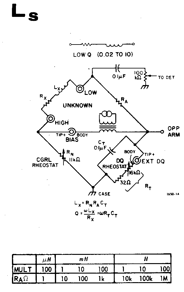
- c. Turn PARAMETER switch to L5.
- d. Connect unknown so that most stray capacitance is between the LOW terminal and the case.
- e. Turn OSC LEVEL cw. The panel control. affects only the internal oscillator. Use full output except for nonlinear unknowns. Iron-core inductors are often nonlinear.
- f. Turn DQ dial full cw.
- g. Set CGRL decade near 5000.
- h. Adjust DET SENS for about 6 divisions deflection.
- i. Turn MULTIPLIER switch for minimum meter reading.
- j. Alternately adjust the CGRL decade and DQ dial for the best null, DQ dial first, increasing the DET SENS as needed. Null means bring the pointer as near to the center of the meter as possible.
- k. If Q is less than 1, the adjustment procedure may become tedious.
- l. If a sharp null cannot be obtained and the Q dial is near 10, switch to Lp.
- m. The series inductance of the unknown equals the product of the CGRL decade reading and the MULTIPLIER-switch setting.
- n. The Q of the unknown is the reading of the third scale (LOW Q) of the DQ dial.
- o. Turn GENERATOR switch OFF.
- a. Turn GENERATOR switch to BAT CHECK 1. If the meter pointer isn't in the BAT sector, replace the batteries in the tube.
- b. Turn GENERATOR switch to AC INTERNAL 1 kHz.
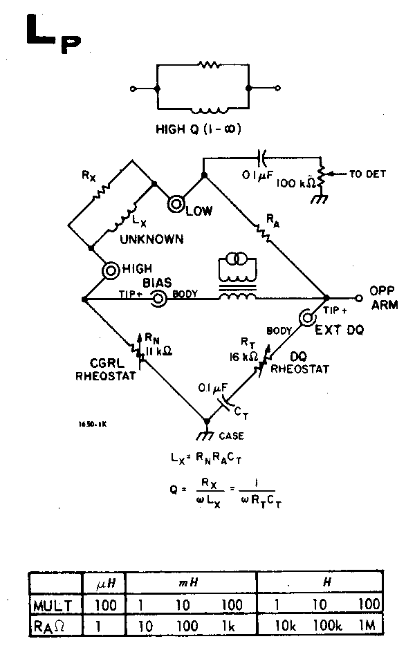
- c. Turn PARAMETER switch to Lp.
- d. Connect unknown so that most stray capacitance is between the LOW terminal and the case.
- e. Turn OSC LEVEL cw. The panel control affects only the internal oscillator. Use full output except for nonlinear unknowns. Iron-core inductors are often nonlinear.
- f. Turn DQ dial fully cw.
- g. Set CGRL decade near 5000.
- h. Adjust DET SENS for about 6 divisions deflection.
- i. Turn MULTIPLIER switch for minimum meter reading.
- j. Alternately adjust the CGRL decade and DQ dial for the best null, CGRL first, increasing the DET SENS as needed. Null means bring the pointer as near to the center of the meter as possible.
- k. If a sharp null cannot be obtained, the unknown is too lossy and must be measured as L5, or the unknown is not inductive.
- I. The parallel inductance of the unknown equals the product of the CGRL decade reading and the MULTIPLIER-switch setting.
- m. The Q of the unknown is reading of the second scale (HIGH 0) on the DQ dial.
- n. Turn GENERATOR switch to OFF.
Dc Resistance.
- a. Turn GENERATOR switch to BAT CHECK 1, then BAT CHECK 2, checking to see that the meter pointer indicates in BAT sector. If the meter pointer in the first check is out of the BAT sector, replace the 4 cells in the tube; if second check is out of the BAT sector, replace the separate cell in the clamp.
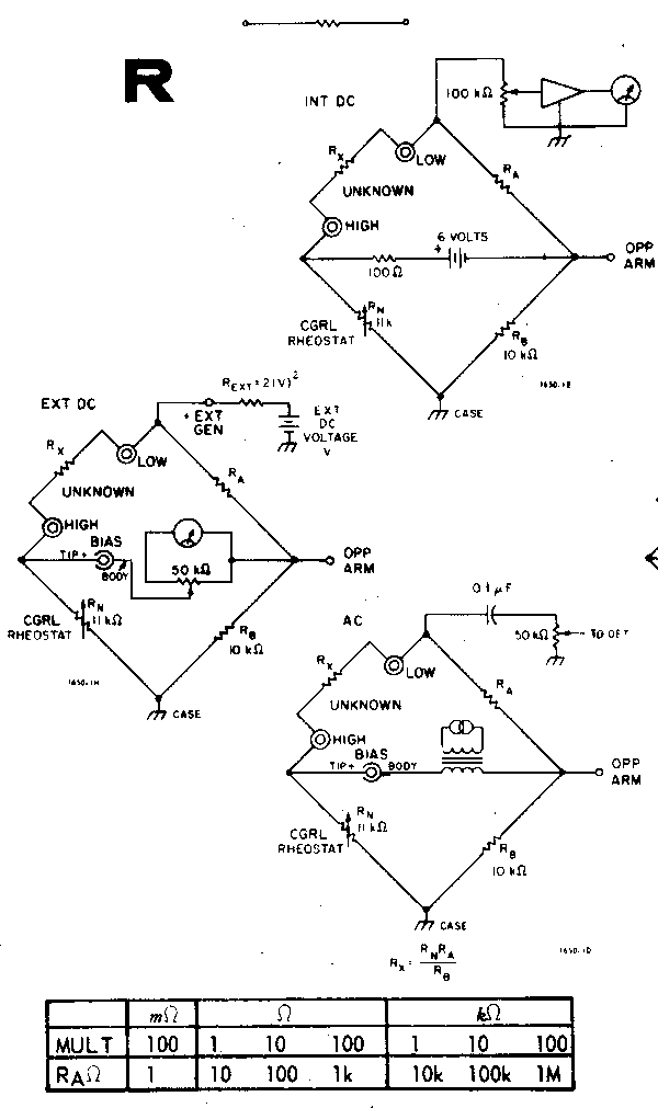
- b. Turn GENERATOR switch to DC INTERNAL and parameter switch to R.
- c. Set CGRL decade to full scale, XXXX.
- d. Set DET SENS control at mid range (spot up).
- e. Turn MULTIPLIER switch full ccw. Then rotate cw one position at a time until the meter deflection reverses direction.
- f. Adjust CGRL decade for best zero (center) deflection, increasing DET SENS if necessary.
- g. Set GENERATOR switch to DC ZERO and adjust ZERO DC knob for new meter reading.
- h. Set GENERATOR switch to DC INTERNAL and repeat balance of main reading.
- i. The unknown resistance is the reading of the CGRL readout multiplied by the MULTIPLIER switch setting.
- j. Turn GENERATOR switch to OFF.
Ac Resistance.
The balancing procedure for the AC resistance is similar to that for C or L except that the R parameter switch portion is used and there is no DQ adjustment.
Dc Conductance.
- a. Turn GENERATOR switch to BAT CHECK 1, then BAT CHECK 2, checking to see that the meter pointer indicates in BAT sector. If the meter pointer in the first check is out of the BAT sector, replace the 4 cells in the tube; if second check is out of the BAT sector, replace the separate cell in the clamp. (see para. 1.3.1
- b. Turn GENERATOR switch to DC INTERNAL and parameter switch to G.
- c. Set CGRL decade to full scale, XXXX.
- d. Set DET SENS control at mid range (spot up).
- e. Turn MULTIPLIER switch full ccw. Then rotate cw one position at a time until the meter deflection reverses direction.
- f. Adjust CGRL decade for best zero (center) deflection, increasing DET SENS if necessary.
- g. Set GENERATOR switch to DC ZERO and adjust ZERO DC knob for new meter reading.
- h. Set GENERATOR switch to DC INTERNAL and repeat balance of main decade.
- i. The unknown conductance is the reading of the CGRL readout multiplied by the MULTIPLIER switch setting.
- j. Turn GENERATOR switch to OFF.
Ac Conductance.
The balancing procedure for the ac conductance is similar to that for C or L except that G parameter switch portion is used and there is no DQ adjustment .
Pius Steiner, 26.Oct.12