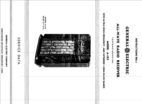
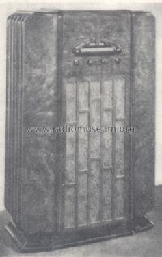
All-Wave A-125
General Electric Co. (GE); Bridgeport CT, Syracuse NY
- Country
- United States of America (USA)
- Manufacturer / Brand
- General Electric Co. (GE); Bridgeport CT, Syracuse NY
- Year
- 1935/1936
- Category
- Broadcast Receiver - or past WW2 Tuner
- Radiomuseum.org ID
- 41985
-
- Brand: Musaphonic


Click on the schematic thumbnail to request the schematic as a free document.
- Number of Tubes
- 12
- Main principle
- Superhet with RF-stage; ZF/IF 465 kHz; 3 AF stage(s)
- Tuned circuits
- 7 AM circuit(s)
- Wave bands
- Broadcast, Long Wave, more than 2 x SW plus FM or UHF.
- Power type and voltage
- Alternating Current supply (AC) / 25 or 60 cycles: 105 - 120 or 115; 125; 220; 240 Volt
- Loudspeaker
- Electro Magnetic Dynamic LS (moving-coil with field excitation coil) / Ø 10.25 inch = 26 cm
- Power out
- 8 W (unknown quality)
- Material
- Wooden case
- from Radiomuseum.org
- Model: All-Wave A-125 - General Electric Co. GE;
- Shape
- Console with any shape - in general
- Dimensions (WHD)
- 26 x 41.875 x 13.875 inch / 660 x 1064 x 352 mm
- Notes
-
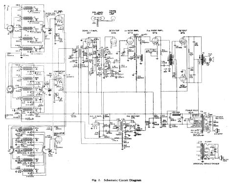
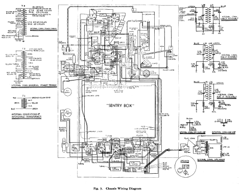
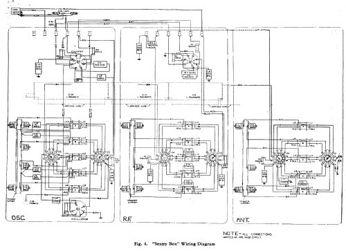
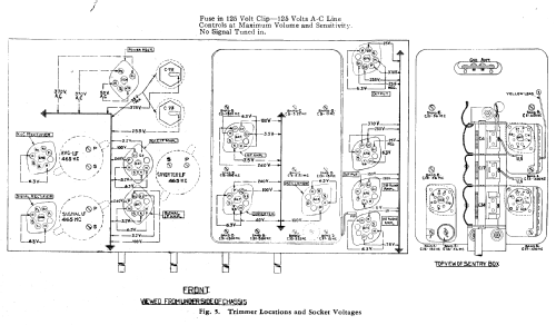
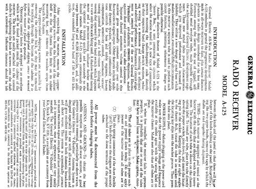
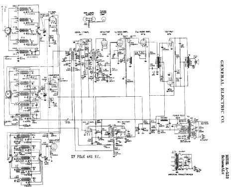
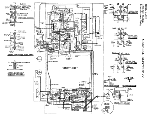
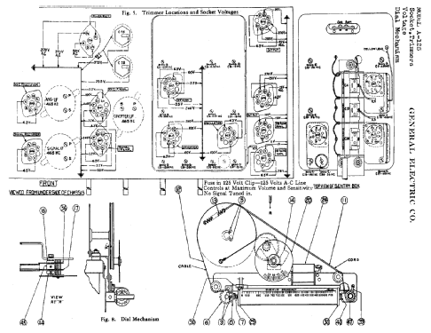
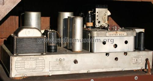
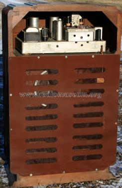
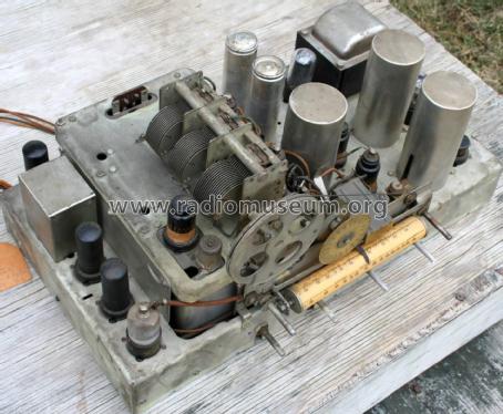
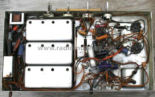
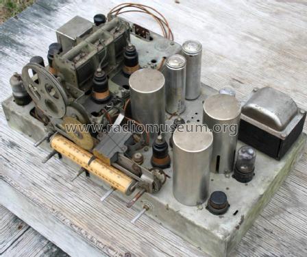
The General Electric All-Wave Radio Receiver A-125 reaches Ultra High-Frequency (up to 40 mc = UHF). As tuning aid the model A-125 uses a shadow type DC milliammeter which indicates the RF amplifier plate current. The A-125 can be fitted with a 25 cycle (C) or 60 cycle mains transformer which came in two versions, one fix for 105-120 volts (A), the other for 105 to 250 volts with 4 tappings (V). The bands are as follows: A (longwave) 140 - 410 kc, B (broadcast) covers 540 - 1740 kc, the band C (Fishery, Police etc.) 1740 - 5800 kc, D 5.6 - 18 mc and band E 18 - 40 mc. See Rider's GE 7-33 through 7-40. The GE Antenna System "Double-Doublet" can be used for all "All-Wave" Radio Receivers and is called no. 9500-A.
- External source of data
- Ernst Erb
- Source of data
- Collector's Guide to Antique Radios 4. Edition
- Circuit diagram reference
- Rider's Perpetual, Volume 7 = 1936 and before
- Mentioned in
- Antique Radios, Johnson 1986
- Literature/Schematics (1)
- Pre-War Consoles
- Literature/Schematics (3)
- General Electric Folder 750M-10-35 for 1935/1936.
- Other Models
-
Here you find 2932 models, 2149 with images and 2061 with schematics for wireless sets etc. In French: TSF for Télégraphie sans fil.
All listed radios etc. from General Electric Co. (GE); Bridgeport CT, Syracuse NY
Collections
The model All-Wave A-125 is part of the collections of the following members.