- Land
- USA
- Hersteller / Marke
- General Electric Co. (GE); Bridgeport CT, Syracuse NY
- Jahr
- 1940–1942
- Kategorie
- Rundfunkempfänger (Radio - oder Tuner nach WW2)
- Radiomuseum.org ID
- 42416
-
- Marke: Musaphonic

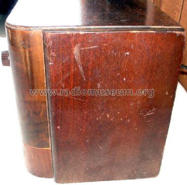
Courtesy ebay seller grandpaczerniak
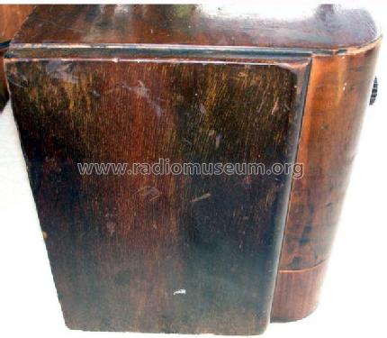
Courtesy ebay seller grandpaczerniak
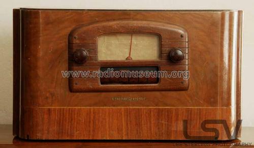
Courtesy ebay seller grandpaczerniak
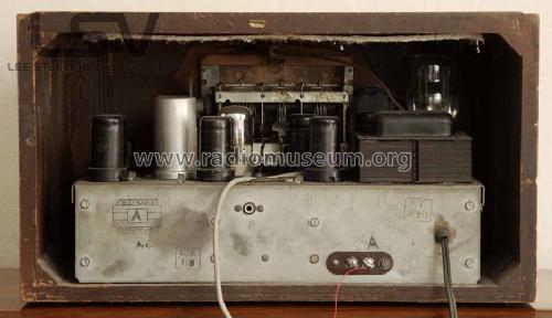
Courtesy ebay seller grandpaczerniak.
Courtesy ebay seller grandpaczerniak
Courtesy ebay seller grandpaczerniak


Klicken Sie auf den Schaltplanausschnitt, um diesen kostenlos als Dokument anzufordern.
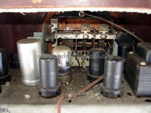
- Anzahl Röhren
- 9
- Hauptprinzip
- Super mit Mehrfachmischung; ZF/IF 23150-27150,4300 kHz; Spezielle Schaltung? Bitte bei Bemerkung nachtragen.
- Anzahl Kreise
- 13 Kreis(e) FM
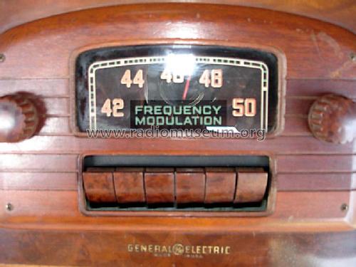
- Wellenbereiche
- UKW-Gerät bzw. FM (keine weiteren Bänder).
- Betriebsart / Volt
- Wechselstromspeisung / 105-125 Volt
- Lautsprecher
- - Für Kopfhörer oder NF-Verstärker
- Material
- Gerät mit Holzgehäuse
- von Radiomuseum.org
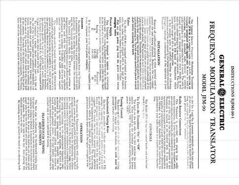
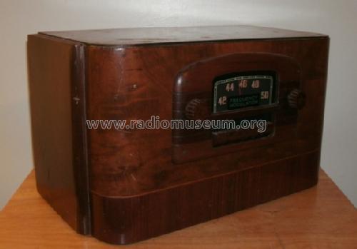
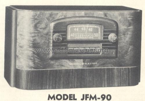
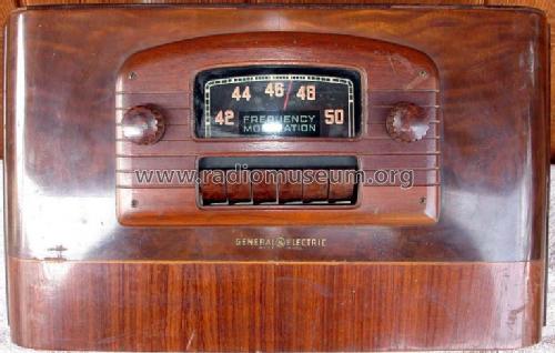
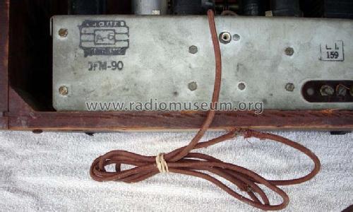
- Modell: JFM-90 - General Electric Co. GE;
- Form
- Tischgerät, Tasten oder Druckknöpfe.
- Abmessungen (BHT)
- 15.5 x 9 x 7.3 inch / 394 x 229 x 185 mm
- Bemerkung
-
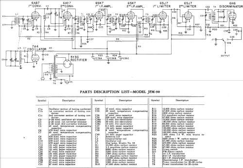
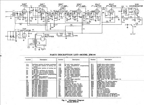
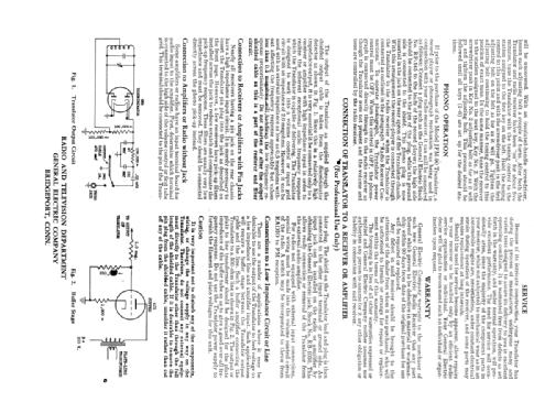
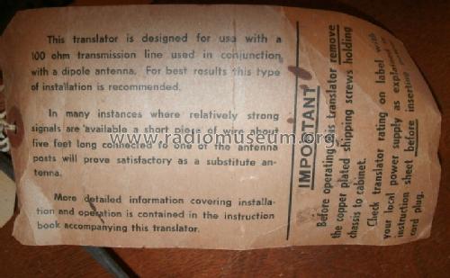
Phonograph or TV Audio connections. John F. Rider 13-76 "OSCILLATOR-CONVERTER CIRCUIT If the full noise reducing properties of frequency modulation are to be realized, the sensitivity of the Translator must be good enough to insure proper limiter operation. The gain through the intermediate frequency circuits is limited to that point beyond which lies instability. Hence a considerable amount of gain must be realized through the R. F. amplifier and converter circuits in order to insure adequate receiver sensitivity. To secure the required gain, the double superheterodyne or cascaded converter circuit is employed. It consists of tow converter tubes 6AB7's and an oscillator tube,7A4, with their associated circuits. The antenna circuit tunes tunes the band from 42 to 50 MC. The circuit between the two converters tunes from 23.15 to 27.15 MC. The oscillator voltage is inductively coupled to the grid of the first converter tube. This produces by heterodyne action a signal to which the inter-converter circuit is tuned. the first converter also conducts the oscillator signal through to the inter-converter circuit. Accordingly, the oscillator signal heterodynes with the tuned signal in the inter-converter circuit to produce an IF frequency of 4.3 MC at the output of the second converter. To illustrate the action consider an FM signal of 42 MC to which the Translator is tuned. The oscillator frequency for this setting of the tuning control is 18.85 MC signal and it heterodynes in the 1st converter tube with the 42 MC signal to form 23.15 MC (42-18.85). This 23.15 MC signal, in turn, beats with oscillator signal in the 2nd converter to produce the 4.3 MC intermediate frequency." Translator here means tuner.
- Datenherkunft extern
- Ernst Erb
- Datenherkunft
- Rider's Perpetual, Volume 13 = 1942 and before
- Schaltungsnachweis
- Rider's Perpetual, Volume 13 = 1942 and before
- Literatur/Schema (1)
- General Electric Radio Service Notes 1939-1942
- Literatur/Schema (2)
- Machine Age to Jet Age II (page 143.)
- Literatur/Schema (3)
- General Electric Folder 13-497-W for 1941.
- Weitere Modelle
-
Hier finden Sie 2953 Modelle, davon 2167 mit Bildern und 2069 mit Schaltbildern.
Alle gelisteten Radios usw. von General Electric Co. (GE); Bridgeport CT, Syracuse NY
Sammlungen
Das Modell JFM-90 befindet sich in den Sammlungen folgender Mitglieder.