C.R. Bridge CR50
Greyshaw Instruments; Brighton
- Land
- Grossbritannien (UK)
- Hersteller / Marke
- Greyshaw Instruments; Brighton
- Jahr
- 1958 ?
- Kategorie
- Service- oder Labor-Ausrüstung
- Radiomuseum.org ID
- 211469
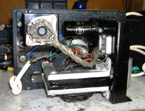
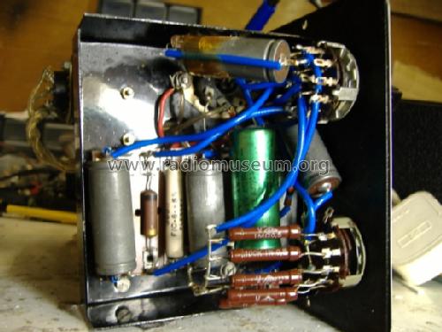
The 6SH7 amplifier and Metal rectifier.
Klicken Sie auf den Schaltplanausschnitt, um diesen kostenlos als Dokument anzufordern.
- Anzahl Röhren
- 2
- Anzahl Transistoren
- Halbleiter
- Tr.Gl.=Metal-rectif.
- Wellenbereiche
- - ohne
- Betriebsart / Volt
- Wechselstromspeisung / 240 Volt
- Lautsprecher
- - - Kein Ausgang für Schallwiedergabe.
- Material
- Metallausführung
- von Radiomuseum.org
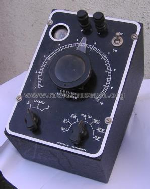
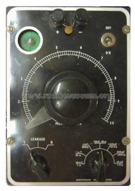
- Modell: C.R. Bridge CR50 - Greyshaw Instruments; Brighton
- Form
- Tischmodell, Zusatz nicht bekannt - allgemein.
- Abmessungen (BHT)
- 195 x 160 x 210 mm / 7.7 x 6.3 x 8.3 inch
- Bemerkung
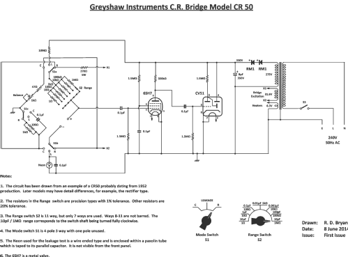
- Dual function CR Bridge and leakage tester:
1) Capacitor and resistor Bridge with 7 ranges, 10 pF - 100 uF and 1 Ohm - 10 MOhm
2) Leakage tester 10 MOhm - 1 GOhm
Uses a relaxation oscillator with capacitor and neon on one terminal and HT via high value resistor on the other test terminal. Neon flash frequency indicates leakage (100 MOhm ~ 1 Hz, 10 MOhm ~ 10 Hz, approx. values). The neon is coupled to the Magic Eye which mimics the terminal voltage on the neon (in bridge mode the Magic Eye indicates the balance null).
- Nettogewicht
- 2.5 kg / 5 lb 8.1 oz (5.507 lb)
- Autor
- Modellseite von Michael Watterson angelegt. Siehe bei "Änderungsvorschlag" für weitere Mitarbeit.
- Weitere Modelle
-
Hier finden Sie 2 Modelle, davon 1 mit Bildern und 1 mit Schaltbildern.
Alle gelisteten Radios usw. von Greyshaw Instruments; Brighton
Sammlungen
Das Modell C.R. Bridge befindet sich in den Sammlungen folgender Mitglieder.
Forumsbeiträge zum Modell: Greyshaw Instruments: C.R. Bridge CR50
Threads: 2 | Posts: 2
The cicuit isn't very complicated, so likely can be repaired wihout a schematic.
The Hunts CRB is a similar instrument from 1945 with fewer ranges and neon visble directly instead of driving the Magic Eye. The Hunts CRB also lacks the 6SH7 amplifier. But the schematic can be studied to see the principle of operation.
Michael Watterson, 30.Jan.12
Testing capacitors is not just measuring the value.
Other aspects are:
- ESR (Effective Series Resistance): Lower voltage Power supplies, especially SMPSU
- Dielectric Loss: VHF, UHF and Microwave performance
- Low voltage Leakage: long time constant filters, integrators, low frequency oscillators
- High voltage leakage: Anode to grid coupling, Screen grid with high load resistors (DAF96)
- Breakdown voltage: Correct initial selection. AC is higher peak voltage.
- Power handling / Ripple Current: PSU, high power amplfiers, SMPSU
- Microphonic or piezoelectric effects that may cause noise pickup or distortion.
1. ESR is generally only an issue on PSUs in equipment since 1980s. Rises with age due to temperature, or poor original parts.
2. Dielectric loss is matter of the correct material. In use this will not generally change.
3. Low Voltage Leakage. Again the appropriate type of material is used originally and it is only likely to be an issue with poor quality Tantalum types.
4. This a major issue with many but not all types of paper capacitors over 20 years old. Waxed card case, cracked plastic case and tar cased. Sealed Metal can types from 1940s and later are often fine.
5. Breakdown voltage is related to "4". But many modern 50V ceramic and foil types test fine at 300V. An Electrolytic rated at 25V will show very high leakage on a 300V leakage tester!
6: Capacitors have losses. Don't expect capacitors carrying many amps of AC to run cool. Incorrectly specified parts that meet the voltage ratings can explode at high AC current!
See Capacitor Leakage tester made from flash gun inspired by this tester. The CR50 puts about 200V across a capacitor with no leakage.
But read the larger full article by Emilio Ciardiello to understand the issues of capacitor leakage and some simple diagnostics.
Don't automatically replace certain types of capacitors! Always test first if in doubt.
Michael Watterson, 30.Jan.12