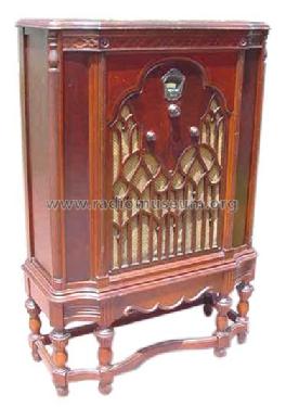
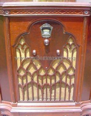
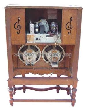
Majestic 310-B Twin Speaker
Grigsby-Grunow (-Hinds) Co. (Majestic pre 1933); Chicago (IL)
- Produttore / Marca
- Grigsby-Grunow (-Hinds) Co. (Majestic pre 1933); Chicago (IL)
- Anno
- 1932 ??
- Categoria
- Radio (o sintonizzatore del dopoguerra WW2)
- Radiomuseum.org ID
- 43633


Ebay 260638152281

Ebay 260638152281
Ebay 260638152281
Ebay 260638152281
Ebay 260638152281
Clicca sulla miniatura dello schema per richiederlo come documento gratuito.
- Numero di tubi
- 7
- Principio generale
- Supereterodina con stadio RF; ZF/IF 175 kHz
- N. di circuiti accordati
- 6 Circuiti Mod. Amp. (AM)
- Gamme d'onda
- Solo onde medie (OM).
- Tensioni di funzionamento
- Alimentazione a corrente alternata (CA) / 110 Volt
- Altoparlante
- AP elettrodinamico (bobina mobile e bobina di eccitazione/di campo)
- Radiomuseum.org
- Modello: Majestic 310-B Twin Speaker - Grigsby-Grunow -Hinds Co.
- Fonte esterna dei dati
- Ernst Erb
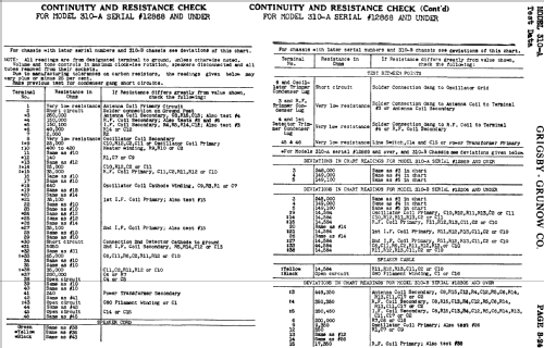
- Riferimenti schemi
- Rider's Perpetual, Volume 3 = 1933 and before
- Bibliografia
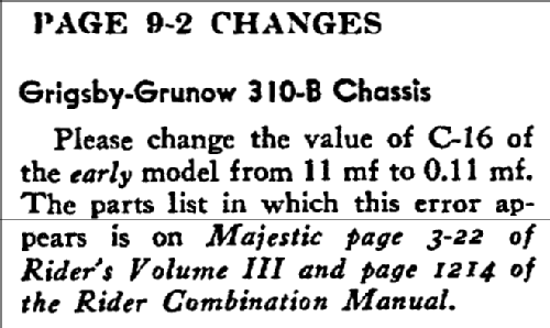
- Rider's Changes 9-2
- Altri modelli
-
In questo link sono elencati 201 modelli, di cui 123 con immagini e 157 con schemi.
Elenco delle radio e altri apparecchi della Grigsby-Grunow (-Hinds) Co. (Majestic pre 1933); Chicago (IL)
Discussioni nel forum su questo modello: Grigsby-Grunow -: Majestic 310-B Twin Speaker
Argomenti: 1 | Articoli: 3
The capacitor bypass block is not labeled at least not in any documentation that I can find.
It has 8 capacitors inside and has10 wires and 3 terminals.
I'm hoping someone can help me determine which wire/terminal belongs to which capacitor. I want to replace all of them. I have toyed with idea of taking the block out opening it up to see if each one is labled inside.
I'm attaching photos and a sketch I made showing where the wires/terminal go.
Any help/advice would be greatly appreciated.
Jim
Allegati
- CapByPass_Block (241 KB)
- CapByPass_Block2 (248 KB)
- CapByPass_Block3 (289 KB)
- Majestic310B_Sketch (151 KB)
James Hochstetler, 26.Feb.22