Drucktasten-Boy 55E
Grundig (Radio-Vertrieb, RVF, Radiowerke); Fürth/Bayern
- Country
- Germany
- Manufacturer / Brand
- Grundig (Radio-Vertrieb, RVF, Radiowerke); Fürth/Bayern
- Year
- 1955
- Category
- Broadcast Receiver - or past WW2 Tuner
- Radiomuseum.org ID
- 173876
-
- alternative name: Grundig Portugal || Grundig USA / Lextronix

Grundig Boy 55E, vista frontale
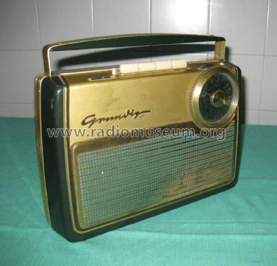
Grundig Boy 55E, vista frontale

Grundig Boy 55E, retro

Grundig Boy 55E

Radio grundig Boy 55E con valigetta


Grundig Boy 55E

Grundig Boy 55E, valigetta aperta vuota
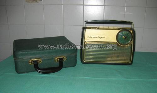
Grundig Boy 55E con valigetta

Grundig Boy 55E
Grundig Boy 55E
Grundig Boy 55E

Grundig Boy 55E
Grundig Boy 55E

Grundig Boy 55E
Grundig Boy 55E

- Number of Tubes
- 4
- Main principle
- Superheterodyne (common); 2 AF stage(s); Export model
- Tuned circuits
- 6 AM circuit(s)
- Wave bands
- Broadcast plus 2 Short Wave bands.
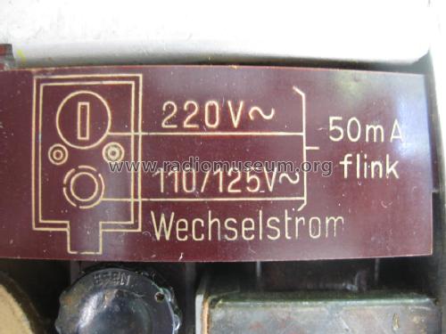
- Power type and voltage
- Line / Batteries (any type) / 110; 125; 220 / DEAC (1,5) & 100 Volt
- Loudspeaker
- Permanent Magnet Dynamic (PDyn) Loudspeaker (moving coil) - elliptical
- Material
- Plastics (no bakelite or catalin)
- from Radiomuseum.org
- Model: Drucktasten-Boy 55E - Grundig Radio-Vertrieb, RVF,
- Shape
- Portable set > 8 inch (also usable without mains)
- Dimensions (WHD)
- 263 x 194 x 91 mm / 10.4 x 7.6 x 3.6 inch
- Notes
- Grundig Drucktasten-Boy 55E is an export model.
Reception ranges:
SW1 3.3...6.25 MHz
SW2 6.25...16 MHz
MW/BC 515...1620 kHz
Ferrite rod antenna for all ranges.
Colors: green or ivory.
Similar to Drucktasten-Boy I/55 which features short, medium (BC) and long waves.
- Net weight (2.2 lb = 1 kg)
- 3.2 kg / 7 lb 0.8 oz (7.048 lb)
- Literature/Schematics (1)
- -- Original prospect or advert
- Author
- Model page created by Bernhard Nagel. See "Data change" for further contributors.
- Other Models
-
Here you find 6251 models, 5496 with images and 4255 with schematics for wireless sets etc. In French: TSF for Télégraphie sans fil.
All listed radios etc. from Grundig (Radio-Vertrieb, RVF, Radiowerke); Fürth/Bayern
Collections
The model Drucktasten-Boy is part of the collections of the following members.
Forum contributions about this model: Grundig Radio-: Drucktasten-Boy 55E
Threads: 1 | Posts: 4
Fellow Radiophiles,
I am trying to identify this portable Grundig radio that seems to be part of a large family of portable radios from the 1950's, but does not seem to have a model page. Similar radio models are named "Drucktasten-Boy", which translates to "Push-button-Boy".
Ross Hochstrasser gave me this radio last week and I got it fixed up today. Thanks, Ross.

The tube lineup is: DK96 DF96 DAF96 DL96. The first three tubes are in this sequence under the right side of the ferrite rod, and the DL96 is plainly visible to the right of the volume control.

The top controls in order:
Volume-power thumb wheel
Charging indicator round rod
Charging button square push button
Three band switch push buttons marked I II III:
I-SW 3.5MHz to 6MHz
II-AM 550kHz to 1600kHz
III-SW 6.5MHz to 16MHz (There is no long wave)
Tone thumbwheel switch
Multiturn tuning thumb wheel (very nice)
Antenna banana jack.

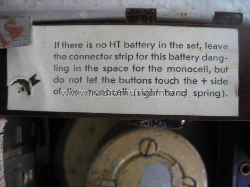
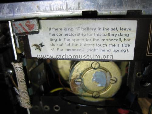
There is a DEAC 1.2V 1.7Ah NiCd accumulator, and space for a 1.5V primary cell to power the four parallel wired filaments.
The high voltage supply has a full wave selenium bridge, and the low voltage supply has a half wave single selenium diode painted red, driving 6V into a 22 Ohm resistor to charge the accumulator to 1.4V. Some of the similar models use a light bulb instead of the 22 Ohm resistor.
The elastic band is still good, and would hold the 90V primary battery.

View of the chassis front:


The similar model Grundig Drucktasten Boy 56 is listed as LW-MW-SW, but the first photo on the model page shows a green radio with the same dial as my radio with SW1-MW-SW2. This photo seems uploaded to the wrong page. Perhaps it belongs on a new model page with my radio.
A few repair notes
The DK96 pentagrid converter was bad, showing about +5V at the control grid G1. The DK96 has been so far the tube I have found most frequently bad or weak, in the 4 portables I have found it in, so far. When this tube gets weak, it's local oscillator stops and all reception ceases, except for some static.
 I removed the DEAC accumulator and cleaned all it's corrosion with a submersion in clear vinegar for a few minutes. This disolved all the white powdery corrosion, and does not seem to affect the paper label. Then, I rinsed with clean water to eliminate any vestige of vinegar. I dried the DEAC with a small fan to prevent new corrosion and to prevent damage to the paper label.
The cleaned DEAC is internally open, so I wired it back in the original slot to preserve the history of the radio.
The accumulator function of the DEAC is now performed with a small sub-C NiMH cell with a 4200mAh capacity. In addition to powering the filaments under battery power, it also serves to regulate and filter the hum from the filament voltage under AC power. Runing the radio without the NiCD or the NiMH accumulator will force too much current into the filaments, along with a lot of hum. The primary 1.5V cell makes a poor regulator because it easily lets the filament supply rise to 1.6V.
I used one of the existing chassis screws to ground the minus tab of the cell, and ran a wire from the plus tab to the same point as the original plus terminal of the old DEAC.
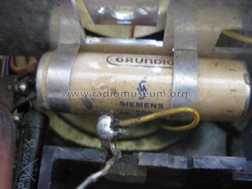
The 500uF cap at the 6V supply was open. I added a 1000uF in parallel. This value will increase the charging current somewhat. If the selenium rectifier can handle the increase current, the NiMH should have no problem absorbing the slightly higher charging current.
The measured charging current with the radio ON is 60mA, and 190mA with the radio OFF.
The measured ripple at the 6V supply is 2.4Vp-p. This ripple should be nearly twice that, around 4Vp-p if the filter cap were the original 500uF value. The average DC would also drop about 1V to 5V, thus reducing the available charging current about 20%. I think the 1000uF will be OK.
 The ferrite rod was broken into two pieces near the center. I glued it back wtih JB-weld epoxy. This epoxy is nearly the same color as the ferrite and is designed for metals. I chose the slow curing version because it is stronger. I held the rod in place during the epoxy cure with heat shrink tubing, a clamp and a thin elastic to keep the two halves well mated.
I have not re-aligned the radio, but it seems to play well on all bands. I have found that a break in a ferrite rod usually has a small effect in the RF circuit alignment. This small effect be easily corrected by moving the coils on the Ferrite rod to get best reception on the low end of each band.
I made a quick check on the alignment of the Ferrite by bringing alternately a small piece of ferrite and a small piece of brass near the end of the rod where the AM band coil is to see if the signal would increase. It dropped in both cases, so the glued ferrite appears to be well aligned and as good as new.
Regards,
-Joe
Joe Sousa, 09.May.10