Halowat TR5 Version 2
Hallock & Watson Radio Corp.; Portland, Oregon (Halowat)
- Country
- United States of America (USA)
- Manufacturer / Brand
- Hallock & Watson Radio Corp.; Portland, Oregon (Halowat)
- Year
- 1926
- Category
- Broadcast Receiver - or past WW2 Tuner
- Radiomuseum.org ID
- 43926
-
- Brand: Halowat


Picture courtesy of Antique radios.com
Picture courtesy of Antique radios.com

Picture courtesy of Antique radios.com

Ebay Item number: 251019507645

Ebay Item number: 251019507645

Ebay Item number: 251019507645

Ebay Item number: 251019507645


- Number of Tubes
- 5
- Main principle
- TRF without regeneration; 2 AF stage(s)
- Tuned circuits
- 3 AM circuit(s)
- Wave bands
- Broadcast only (MW).
- Power type and voltage
- Storage and/or dry batteries / 6 & 4.5 & 3 x 45 Volt
- Loudspeaker
- - This model requires external speaker(s).
- Material
- Wooden case
- from Radiomuseum.org
- Model: Halowat TR5 [Version 2] - Hallock & Watson Radio Corp.;
- Shape
- Tablemodel, Box - most often with Lid (NOT slant panel).
- Notes
-
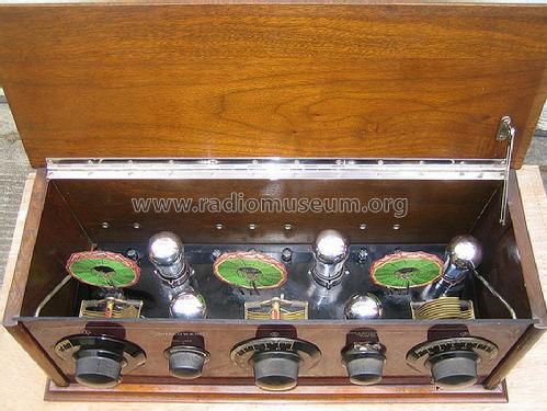
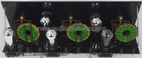
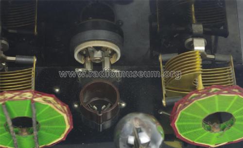
The Halowat TR-5 is a battery operated 5 tube BC band receiver. There were several different versions of the TR-5.
The following batteries are required for operation of this radio:
A Battery - 6V
B Battery - Either Qty(3) 45V batteries or Qty(1) 135V battery with taps at 45V and 90V
C Battery - 4.5VTR-5 Model Differences:
Model Year Output Tube
Wavelength Control Variable Capacitors Front Panel Operating Instructions TR-5 Ver. 1 1925 UV201A Rheostat with round graduated knob Counter weighted from General Radio Black Came with instruction manual TR-5 Ver. 2 1926 UX112A 3 tap switch Low loss type from Premier Co., Crowfoot Brand Red Came with instruction card TR-5 Ver. 3 1926 UX112A 3 tap switch Low loss type from Premier Co., Crowfoot Brand Brown, no phone jacks on front panel, ON/OF switch moved
- Price in first year of sale
- 90.00 $
- External source of data
- Ernst Erb
- Source of data
- Radio Collector`s Guide 1921-1932
- Other Models
-
Here you find 14 models, 8 with images and 0 with schematics for wireless sets etc. In French: TSF for Télégraphie sans fil.
All listed radios etc. from Hallock & Watson Radio Corp.; Portland, Oregon (Halowat)
Collections
The model Halowat is part of the collections of the following members.
Forum contributions about this model: Hallock & Watson: Halowat TR5
Threads: 2 | Posts: 2
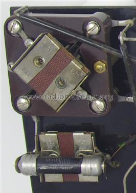
AUDIO OUTPUT JACK’S
CONFIGURATION
HALOWAT TR-5 Version 2
The left hand jack, labeled loud, which is a single-circuit jack, is used to conduct the plate current from the Second audio tube (UX 112), to the loudspeaker. This jack has the additional feature of serving as a switch in the filament line to turn on the second Audio Tube (UX 112), when the loudspeaker is plugged in. Thus, when this jack is not in use total power consumption is reduced.

The centre jack, labeled medium, is used for headphone reception from long-distance stations or loudspeaker reception of nearby stations, enough volume being obtained without the use of the Second Audio Tube (UX 112). In such a double-jack arrangement the filament of the Second Audio Tube (UX 112) is automatically disconnected when the plug is removed from the left hand jack labeled loud.
Bruce Morgenstern
Bruce Morgenstern, 09.Jan.15
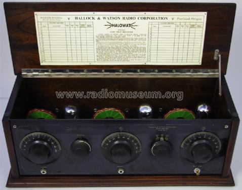
-----HALOWAT-----
Instructions
Type “TR-5” receiver (Version 2)
CAUTION: CONNECT ALL BATTERY WIRES TO RECEIVER BEFORE CONNECTING BATTERIES THEMSELVES. THEN CHECK THEM AGAIN TO BE SURE YOU ARE RIGHT BEFORE CONNECTING TO BATTERY POSTS.
The aerial should be around 75 feet long in the horizontal part and as high as possible. The ground should be as short, direct and low resistance as can be made. Fasten firmly to the water pipe AS NEAR AS POSSIBLE TO WHERE IT ENTERS THE SOIL. USE COPPER WIRE.
Use four 201-A, (301-A) or any good independent tube with the same characteristics. THE “SECOND AUDIO” TUBE (REAR LEFT SOCKET) MUST BE A UX 112. The “A” battery is the standard six volt storage and the “B” battery must be 135 volts tapped off at 45 and 90 as the binding post show. The “C” battery should be a single 4 ½ volt block.
With battery connections made as indicated on binding posts and loudspeaker connected to proper posts turn all 3 dials to approximately 48, put 3-point switch on “M” and turn volume rheostat about three-quarters on. In this condition slowly swing No. 1 dial between about 40 and 50 until maximum signal from KGO, Oakland is obtained. When you have determined position for No. 1 dial, vary No. 2 and No. 3 just slightly and then adjust signal intensity with the volume rheostat. It will be found that No. 2 and No. 3 dials operate practically together throughout the entire wave length, No. 1 varying somewhat with the antenna.
Generally speaking the 3-point switch is left on “S” for stations up to about 35° on the dials on “M” from there to about 60° and on “L” for the balance, that is 60 to 100°. The volume and quality are controlled by the volume rheostat entirely which handles the two radio frequency tubes. The detector and 2 audio filaments are handled by a fixed resistance in the base of the receiver, which is set for 2 201As and 1 UX-112.
The proper setting of the “volume” rheostat is always the point just below where the tubes will go into oscillation. This will vary somewhat, depending on whether the switch is on “S” “M” or “L,” and a little practice will bring the desired results.
NOTE: The wording of this document was taken, verbatim, from the "INSTRUCTION CARD" on the lid of the Halowat TR-5 Version 2, 1926.
Bruce Morgenstern
Bruce Morgenstern, 08.Jan.15