HQ-110A-VHF 3rd serial run >7000
Hammarlund Mfg. Co. Inc.; New York, NY
- Land
- USA
- Hersteller / Marke
- Hammarlund Mfg. Co. Inc.; New York, NY
- Jahr
- 1958–1969
- Kategorie
- Amateur-Empfänger (Amateur-Bänder, zudem auch Rundfunkbänder möglich)
- Radiomuseum.org ID
- 208890
By courtesy of Bill Henry, Deland, FL, USA.
By courtesy of Bill Henry, Deland, FL, USA.

By courtesy of Bill Henry, Deland, FL, USA.

By courtesy of Bill Henry, Deland, FL, USA.
By courtesy of Bill Henry, Deland, FL, USA.
- Anzahl Röhren
- 11
- Hauptprinzip
- Super mit HF-Vorstufe; 2 NF-Stufe(n)
- Wellenbereiche
- Wellen in den Bemerkungen.
- Betriebsart / Volt
- Wechselstromspeisung / 115 Volt
- Lautsprecher
- - Dieses Modell benötigt externe(n) Lautsprecher.
- Belastbarkeit / Leistung
- 1 W (Qualität unbekannt)
- Material
- Metallausführung
- von Radiomuseum.org
- Modell: HQ-110A-VHF [3rd serial run >7000] - Hammarlund Mfg. Co. Inc.; New
- Form
- Tischgerät-gross, - Querformat (breiter als hoch oder quadratisch).
- Abmessungen (BHT)
- 418 x 231 x 232 mm / 16.5 x 9.1 x 9.1 inch
- Bemerkung
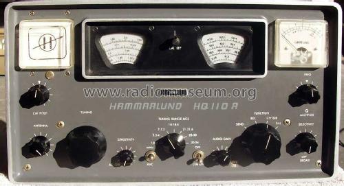
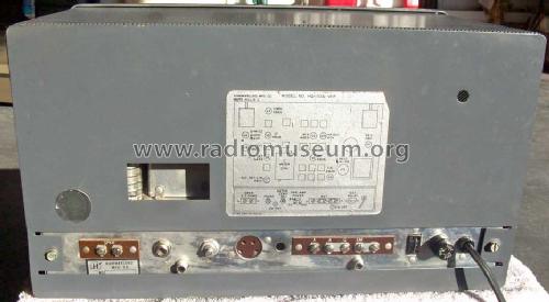
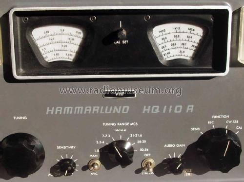
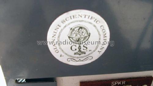
- The Hammarlund model HQ-110A is a HAM bands receiver for 6, 10, 15, 20, 40, 80 and 160 Meters. Optional 2 meters VHF converter and "Telechron Auto-Timer" clock. There are different variants: On the outside one can distinguish the first series HQ-110A by a small metal tag that says HQ 110A between the two scales, the HQ-110AE is a dual voltage Export-Version (perhaps for each run), the normal run two and this one, the HQ-110A-VHF, which has s metal tag on the front with "VHF" and below a silkscreen with "HAMMARLUND HQ 110 A". This model has a pre-amp on 2 & 6 meters. We believe it is the last of the series. See the small sticker on the rear of the case, indicating that it was built by the "Gianianni Scientific company", the last company that owned Hammarlund before they closed.
Production Changes (by Bill Henry, Deland, FL, USA):
The HQ-110 was produced in at least 3 serial number ranges. The first run includes serial numbers up to 4199; the second run includes serial numbers from 5000 to 7000; and the final run includes serial numbers above 7000. The serial number can be found stamped into the rear apron of the chassis.
The major changes in the second serial run are in the area of V1 and V2 and in the BFO circuit. The coupling arrangement between T1 and T2 was modified significantly, as were parts of the second mixer circuit. The second mixer crystal was changed from a 3.49 Mc to 2.58 Mc. Also, there were finally some further attempts at temperature compensation to help to reduce the inherent drift of the receiver. In addition, the BFO circuit was changed considerably so that its output comes from the plate rather than from the cathode as previously done.
In the third serial run, there were further changes in the T1/T2 coupling as well as new changes in the RF stage and the second mixer. Most notably, the Antenna coils are no longer gang-tuned to the mixer and local oscillator. The antenna coils are now resonated by the antenna trimmer only, leaving the main tuning capacitor a 2-section variable, rather than a 3-section as it was previously. According to a Product Addendum covering the second and third runs, 6 capacitors were added to improve stability in the high frequency oscillator and BFO sections; 2 coils were added to the second mixer and local oscillator to improve stability; and a resistor across the output transformer was added to provide an emergency speaker load.
- Nettogewicht
- 11.4 kg / 25 lb 1.8 oz (25.11 lb)
- Autor
- Modellseite von Ernst Erb angelegt. Siehe bei "Änderungsvorschlag" für weitere Mitarbeit.
- Weitere Modelle
-
Hier finden Sie 144 Modelle, davon 92 mit Bildern und 58 mit Schaltbildern.
Alle gelisteten Radios usw. von Hammarlund Mfg. Co. Inc.; New York, NY