- Produttore / Marca
- HMV (Brand), His Masters Voice, The Gramophone Company Ltd.; Middlesex
- Anno
- 1935
- Categoria
- Radio (o sintonizzatore del dopoguerra WW2)
- Radiomuseum.org ID
- 195899
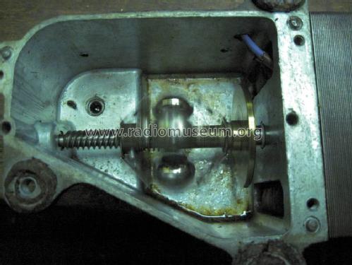
On side wall inside


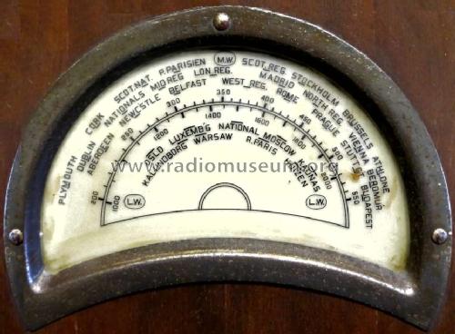
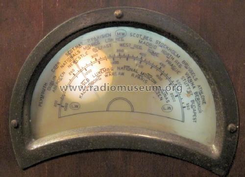
Pointer is behind scale and casts a shadow
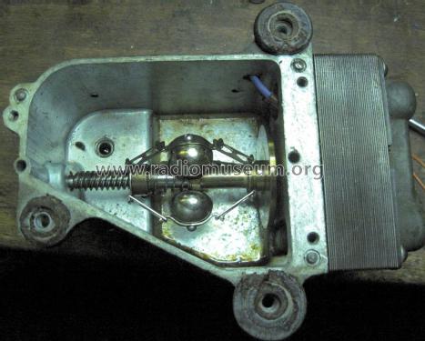
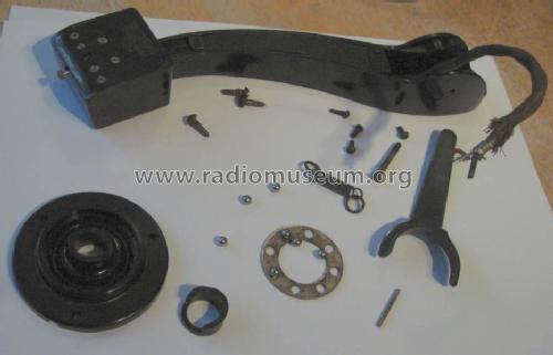
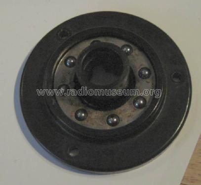
Parts of "tone arm", base is broken.

Clicca sulla miniatura dello schema per richiederlo come documento gratuito.
- Numero di tubi
- 4
- Principio generale
- A circuiti accordati (TRF o amplif. diretta in generale)
- Gamme d'onda
- Onde medie (OM) e onde lunghe (OL).
- Particolarità
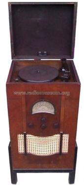
- Giradischi o cambiadischi
- Tensioni di funzionamento
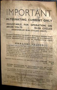
- Alimentazione a corrente alternata (CA) / 200-250 Volt
- Altoparlante
- AP elettrodinamico (bobina mobile e bobina di eccitazione/di campo)
- Materiali
- Mobile in legno
- Radiomuseum.org
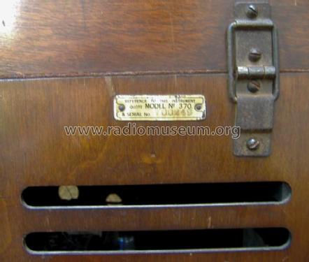
- Modello: 370 - HMV Brand, His Masters Voice,
- Annotazioni
-
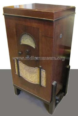
Similar to the Marconiphone 245 radiogram.
The scale is translucent with the tuning pointer behind it. A lamp is mounted behind the pointer travelling with it to cast a shadow on the scale.
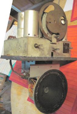
The record player pickup uses steel needles. Its speed is adjustable and there is an auto-stop mechanism.
Access to the Radio Chassis is by removal of the top record player assembly.
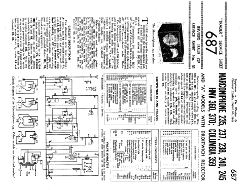
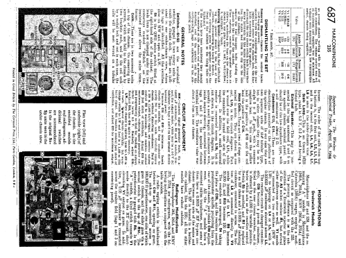
- Letteratura / Schemi (1)
- Trader sheet 687
- Autore
- Modello inviato da Howard Craven. Utilizzare "Proponi modifica" per inviare ulteriori dati.
- Altri modelli
-
In questo link sono elencati 420 modelli, di cui 329 con immagini e 242 con schemi.
Elenco delle radio e altri apparecchi della HMV (Brand), His Masters Voice, The Gramophone Company Ltd.; Middlesex
Discussioni nel forum su questo modello: HMV Brand, His: 370
Argomenti: 2 | Articoli: 2
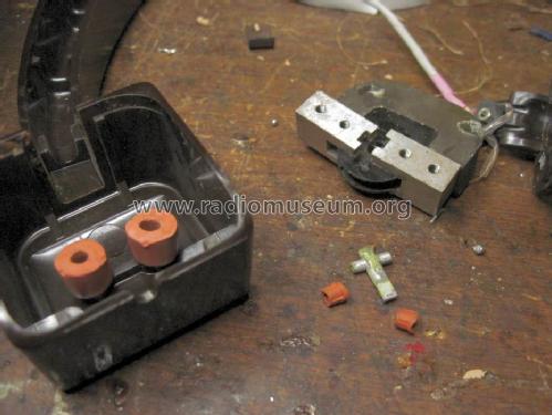
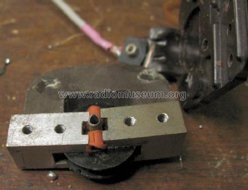
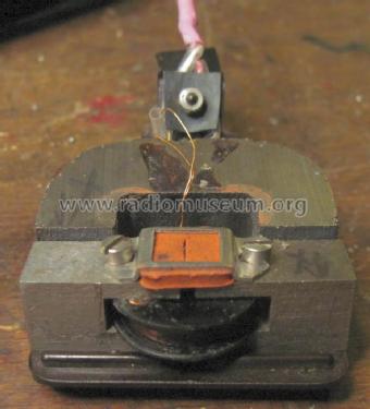
The needle holder is the "moving iron" as I can confirm it plays with a Bamboo "needle".
Michael Watterson, 16.May.14
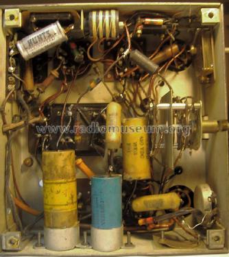
The radio doesn't use a true volume control. Instead the "volume" control potentiometer (on right) is V1 bias (quite common on late 1920s & early 1930s) and to an extent the "reaction control" capacitor (on left).
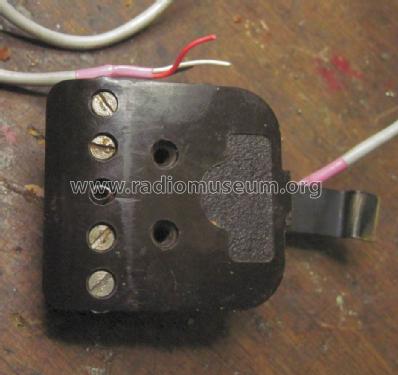
The chassis was modified for Gramophone use by adding three wander sockets (pair nearest side of chassis are both "earth" and 3rd is signal) and 1 M Ohm pot ganged with R5 (14 K Ohm) the V1 Bias / "volume". Extra switch contacts are supposed to be used to connect the silder of the extra 1M Pot fed by 3rd wander plug socket and disconnect C10 from V2 detector. Except on my model the Radio "muting" is very poor (on the 370A and related models they also short V2 anode to HT to provide more Radio muting!) and the ganged pot is missing.
The turntable panel was hacked on rear (long ago, perhaps even in 1930s or 1940s) to add a 1M volume control there. The input socket appears to be aways connected to junction of R12 & R11 as turning the "deck" volume down controls radio volume!
Perhaps the solution is to buy both 20K and 1M stereo pots and swap the backs to have a 1M & 20K (close enough to 14K as it's open one end) dual gang and examine switch wiring. Then fill hole in top panel. The pick up is "floating" pair with an overall screen. The 3 sockets on chassis rear is common earth for screen and one signal wire.
The moving iron Pickup coil uses unbelievably fine wire, with about 42500 Ohms (42K5!) on about a 15mm bobbin about 5mm tall winding.
See photos of arm and pickup assembly and sockets under chassis (top left of image sockets, left side of image is rear)
Michael Watterson, 15.May.14