784 Ch= 784
Howard Radio Pty. Ltd.; Richmond VIC
- Country
- Australia
- Manufacturer / Brand
- Howard Radio Pty. Ltd.; Richmond VIC
- Year
- 1937
- Category
- Broadcast Receiver - or past WW2 Tuner
- Radiomuseum.org ID
- 171871


Front view with door open

Back View

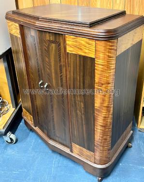
Front view with door closed

Model number label

Closeup of dial
Side view
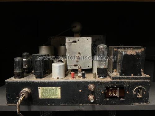
Chassis label

Click on the schematic thumbnail to request the schematic as a free document.
- Number of Tubes
- 9
- Main principle
- Superhet with RF-stage; ZF/IF 460 kHz; 3 AF stage(s)
- Tuned circuits
- 9 AM circuit(s)
- Wave bands
- Broadcast plus more than 2 Short Wave bands.
- Power type and voltage
- Alternating Current supply (AC) / 200-260 Volt
- Loudspeaker
- Electro Magnetic Dynamic LS (moving-coil with field excitation coil) / Ø 12 inch = 30.5 cm
- Material
- Wooden case
- from Radiomuseum.org
- Model: 784 Ch= 784 - Howard Radio Pty. Ltd.;
- Shape
- Console, Lowboy (legs < 50 %).
- Notes
-
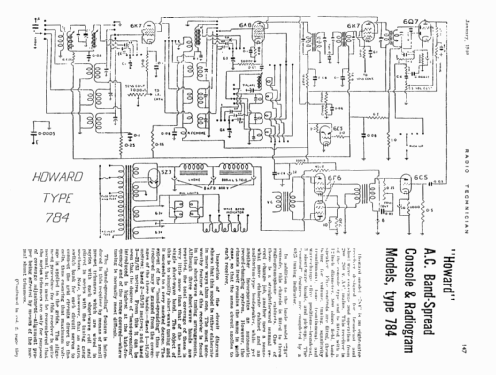
HOWARD A.C. OPERATED "BAND-SPREAD" MODEL 784
(FROM RADIO AND ELECTRICAL RETAILER, 30/12/1938.)
Howard model "784" is an eight-valve receiver designed for broadcast and short-wave coverage and operation from 200-260 v. A.C. mains. This receiver is of the console type and is fitted with a 12 inch diameter, 800 ohms field, loudspeaker. five controls are fitted, these being for volume, tuning, sensitivity (continuous), tone (continuous), and wave-change (five positions - broadcast, 3 short-wave bands, and pick-up). The "control" features are completed by a 6E5 tuning indicator.
In addition to the basic model "784" console, this chassis is fitted to two or three radio-gramophone cabinets. One of these is a straightforward manual record change job, another uses a somewhat more eleborate cabinet and an auditorium-type loudspeaker, while yet another incorporates an automatic record-changing system. However, the chassis itself remains the same in each case, so that the same circuit applies to each receiver.
Inspection of the circuit diagram shows that this model is rather elaborate in more ways than one. The most noteworthy feature of this receiver is found in the short-wave tuning arrangement. Although three short-wave bands are provided, the total coverage of these is very little more than that of the usual single short-wave band. The object of this is to simplify short-wave tuning and it succeeds to a very marked degree. The extent of the "band-spreading" thus introduced may be gauged from the coverage of the three bands: - Band 1 - 16/20 metres; band 2 - 19/30 metres; and band 3 - 29/53 metres.From this it can be seen that the degree of "band-spreading" introduced is highest at the high-frequency end of the range covered - where tuning is normally most difficult.
The "band-spreding" feature is introduced in this receiver by means of small pre-set trimmers which are wired in series with each short-wave coil and placed in series with the tuning gang sections. Note, however, that an extra switch bank for each circuit serves to connect the grid circuits direct to the coils, thus ensuring that maximum voltage is applied to the grids. The alignment procedure for this receiver is quite normal, but it must be remembered that the series trimmers are only for purpose of coverage adjustment - alignment proper being effected by means of the normal shunt trimmers.
In addition to the above, attention should be paid to the capacity-coupled band-pass filter which procedes the R.F. stage on the broadcast band; the band-pass I.F. coupler which follows the mixer valve; and the elaborate audio channel. These are all quite straightforward, however, and providing careful attention is paid to the circuit diagram and operating voltages, no trouble should be experienced.
- Literature/Schematics (1)
- Radio & Electrical Retailer, Australia (Vol. 15, No. 23 (322nd Issue), 30/12/1938, Page 10.)
- Literature/Schematics (2)
- Radio Technician (January 1940, page 149.)
- Literature/Schematics (3)
- Mingay's "Radio Diagram & I.F. Index
- Author
- Model page created by Stuart Irwin. See "Data change" for further contributors.
- Other Models
-
Here you find 130 models, 34 with images and 11 with schematics for wireless sets etc. In French: TSF for Télégraphie sans fil.
All listed radios etc. from Howard Radio Pty. Ltd.; Richmond VIC