Mercury Super Ten (DeLuxe) Mercury Super 10 walnut
Kipp Co. Ltd., H.M.; Toronto
- Paese
- Canada
- Produttore / Marca
- Kipp Co. Ltd., H.M.; Toronto
- Anno
- 1925–1927
- Categoria
- Radio (o sintonizzatore del dopoguerra WW2)
- Radiomuseum.org ID
- 105067
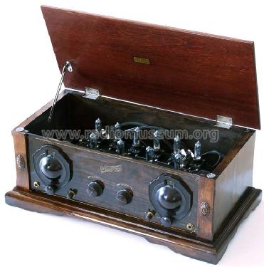

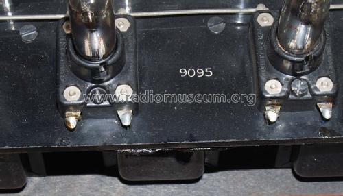
10 gleiche Röhren R215A


Clicca sulla miniatura dello schema per richiederlo come documento gratuito.
- Numero di tubi
- 10
- Principio generale
- Supereterodina (in generale); ZF/IF 247 kHz
- Gamme d'onda
- Onde medie (OM), lunghe (OL) e più di 2 gamme di onde corte (>2 x OC).
- Tensioni di funzionamento
- Batterie (di accumulatori e/o a secco) / 6 & 60 to 135 Volt
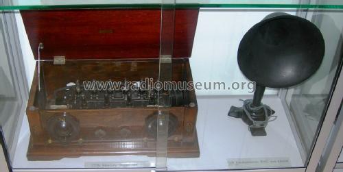
- Altoparlante
- - Questo apparecchio richiede altoparlante/i esterno/i.
- Materiali
- Mobile in legno
- Radiomuseum.org
- Modello: Mercury Super Ten Mercury Super 10 [walnut] - Kipp Co. Ltd., H.M.; Toronto
- Forma
- Soprammobile a cassapanca o cassetta, solitamente con coperchio (NON a leggio)
- Annotazioni
- This version of the Super Ten is also known as the DeLuxe Mercury model - here the walnut variant. See also the Super 10 from 1923 and 1924.
All Super Ten employed 10 "Peanut" tubes - and the radio (included it's siblings) was touted as the most sensitive and selective radio in the mid 1920s. The tubes had cost an extra 30 CDN$. 4 stages of RF/IF, oscillator, 2 detectors, AF tube and 2 power output tubes. Series-parallel filament circuit for the 1.1 volt tubes on a 6 volt accumulator. Thanks to the R215A tubes the set consumes only 500 ma on the "A" battery and a max. of 20 ma on the "B" battery. If 60 volts are used no bias ("C" battery) is needed. The Mercury Super Ten has also been sold as a kit. Customers could buy a loop aerial model "A" for 23.50 CDN$, designed for the Mercury Super Ten. Several prizes were awarded to the Mercury Super Ten (Super 10) for its excellent reception properties.
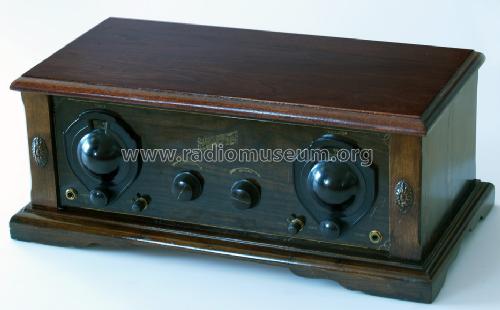
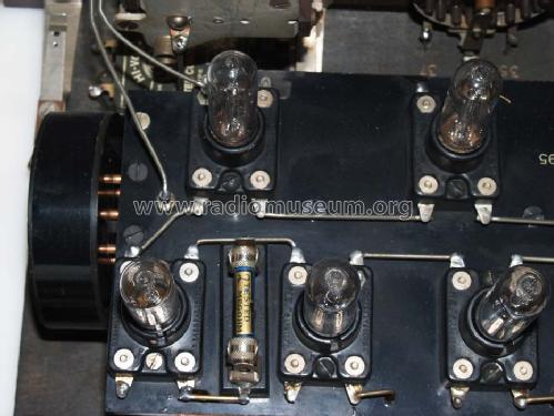
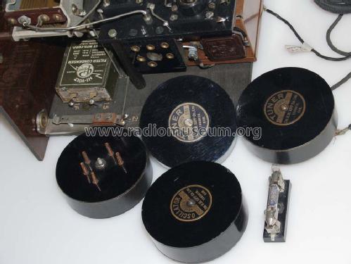
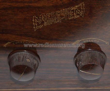
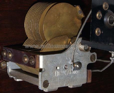
You can differenciate on the front of the wooden bottom if it is a Standard or a DeLuxe model case: The standard swings to the bottom in the middle while the DeLuxe mahogany is straight, the DeLuxe walnut swings upwards. The chassis of the Mercury DeLuxe shows vernier dials and the Standard comes with a "normal" dial. The RF and oscillator coils of the DeLuxe are plug-in couls (at either end), the Standard applies fixed coils. The Mercury Super Ten was made in Toronto at the beginning of 1925. According to Robert P. Murray in "The early development of Radio in Canada" (page 113) C.A. Lowry designed the receiver, a young engineering student. The cabinets were probably made in different places because some variations exist. The "peanut tubes" were designed (1919) as reliable telephone industry repeater tubes. Available were plug in coils for 9-22, 22-32, 32-80, 80-190, 190-550 meters and coils covering wavelengths up to 1000 meters.
- Prezzo nel primo anno
- 165.00 CDN$
- Fonte dei dati
- Radios of Canada; Swackhammer
- Riferimenti schemi
- Radio College of Canada
- Bibliografia
- The Early Development of Radio in Canada 1901-1930 (page 113 to 119)
- Autore
- Modello inviato da Ernst Erb. Utilizzare "Proponi modifica" per inviare ulteriori dati.
- Altri modelli
-
In questo link sono elencati 9 modelli, di cui 5 con immagini e 5 con schemi.
Elenco delle radio e altri apparecchi della Kipp Co. Ltd., H.M.; Toronto
Collezioni
Il modello Mercury Super Ten (DeLuxe) fa parte delle collezioni dei seguenti membri.
Discussioni nel forum su questo modello: Kipp Co. Ltd., H.M.;: Mercury Super Ten Mercury Super 10
Argomenti: 1 | Articoli: 2
In the very early days of Radio, Superheterodynes were built quite different from their successors 10 or 20 years later.
They had to apply relatively weak battery triodes throughout, even for the output.
Sensitivity was aimed for, to permit use of frame aerials, thus avoiding wire antennas, e.g. in a city, and benefit from directivity and suppression of electric noise from the environment.
Selectivity was not yet achieved by IF band filters. Either transformers (air or even iron core of thin wires) or some times a single tuned circuit did the job.
Contemporary triodes had some problems at higher frequencies. Hence the IF was chosen between 40 to 100 kc. Consequently image reception was unavoidable.
Here is one of these multi tube monsters (they are my favorites...) : the Kipp Mercury Standard also called the Mercury Super Ten.
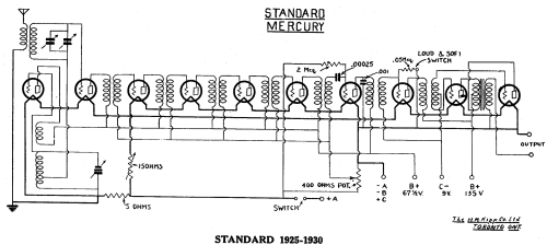
Circuitry analysis, as from the schematic :
Starting at top left, the Antenna input transformer hat the secondary tuned.
Below the oscillator (tube #1) has the Grid circuit tuned. The grid coil is tapped to feed the input circuit in series. Both signals, input and oscillator, are added and fed to the second tube, the 1st Detector or Mixer stage.
The next four IF stages (tubes #3 to #6) are transformer-coupled, followed by the 2nd Detector, an Audion demodulator (tube #7)
Consequently the IF does not contribute to selectivity, but to sensitivity. Tuning is provided by the input circuit, while the oscillator may be set to a frequency which falls in the passband range of the IF transformers, and whereno other station might disturb (image frequency, 2nd harmonic products etc.).
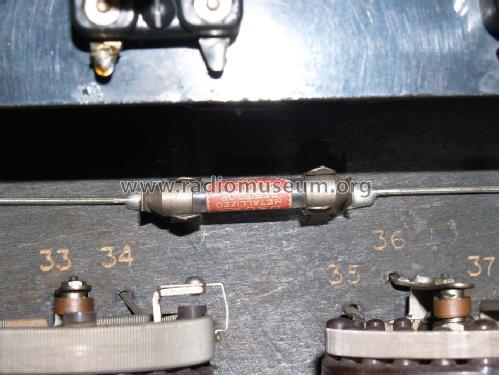
Gain control is achieved by variable grid bias(400 ohms pot.) and filament control (15 ohms variable). It acts at IF and partly 2nd Det.
Osc., 1st Det., and Audio tubes are at full A supply (via 5 ohms in series)
A transformer coupled 1st AF stage (tube #8) is driving the transformer coupled 2nd Audio (tube #9 and #10 in push-pull).
A Loud & Soft switch allows to shunt the secondary of the 1st AF transformer with a 50 kOhm resistor.
The A supply employs two series filament arrangements. That permits use of a standard 6 volt storage battery. The current drawn is ca. 0.5 amps max.
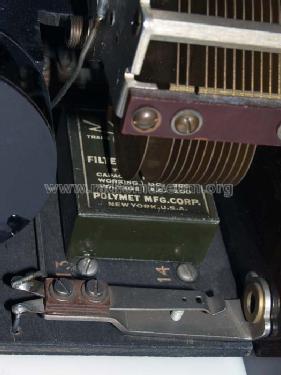
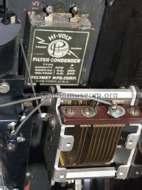
B supply is +67.5 and +135 volts. The latter is the maximum value. It can be less, as sufficient for the desired output.
-C bias has to be set to optimise the currrent drawn from the B battery vs. tone distortion. A tapped C battery of 9 volts will do.
The -C battery might not be required if the output stage works on low voltage.
Antenna reradiation is certainly a problem. The oscillator frequency is going through the input secondary coil to the mixer grid (which certainly draws grid current), plus capacitive coupling to the primary, thus coupling to the aerial. There is no RF stage to decouple. I wonder how that problem was managed those days...
Konrad Birkner † 12.08.2014, 06.Sep.06