- Produttore / Marca
- Allied Radio Corp. (Knight, Roamer, Wextark); Chicago (IL)
- Anno
- 1963
- Categoria
- Radio (o sintonizzatore del dopoguerra WW2)
- Radiomuseum.org ID
- 94697


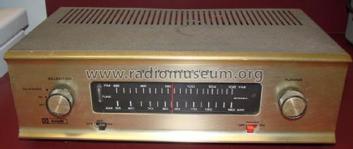
Frontansicht

Gesamtansicht aussen


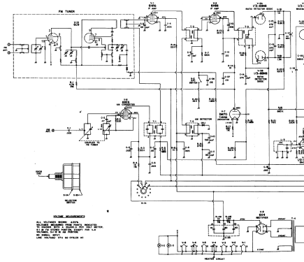
Clicca sulla miniatura dello schema per richiederlo come documento gratuito.
- Numero di tubi
- 10
- Numero di transistor
- Principio generale
- Supereterodina (in generale); ZF/IF 460 kHz; 1 Stadi BF
- N. di circuiti accordati
- 6 Circuiti Mod. Amp. (AM) 11 Circuiti Mod. Freq. (FM)
- Gamme d'onda
- Onde medie (OM) e MF (FM).
- Tensioni di funzionamento
- Alimentazione a corrente alternata (CA) / 117 Volt
- Altoparlante
- - Per cuffie o amplificatori esterni
- Materiali
- Mobile in legno
- Radiomuseum.org
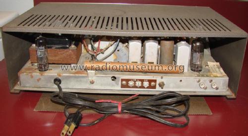
- Modello: Knight KG-50 - Allied Radio Corp. Knight,
- Forma
- Soprammobile con qualsiasi forma (non saputo).
- Dimensioni (LxAxP)
- 372 x 130 x 210 mm / 14.6 x 5.1 x 8.3 inch
- Annotazioni
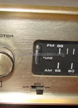
- AM-FM-MX Stereo Tuner.
- Peso netto
- 2.9 kg / 6 lb 6.2 oz (6.388 lb)
- Bibliografia
- -- Original-techn. papers.
- Autore
- Modello inviato da Rolf Nickel. Utilizzare "Proponi modifica" per inviare ulteriori dati.
- Altri modelli
-
In questo link sono elencati 1036 modelli, di cui 639 con immagini e 680 con schemi.
Elenco delle radio e altri apparecchi della Allied Radio Corp. (Knight, Roamer, Wextark); Chicago (IL)
Discussioni nel forum su questo modello: Allied Radio Corp.: Knight KG-50
Argomenti: 1 | Articoli: 1
Dear F...,
at first sorry, my english is not so very good, but I will try to tell you the story. I am not sure if you remember : I purchased by an Ebay auction in September last year your old "Knight KG 50"-tube tuner which you had mounted together with your father in 1963.
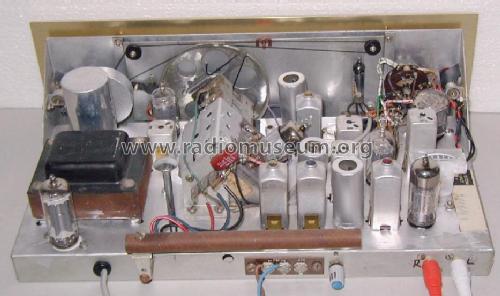
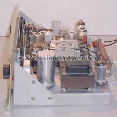
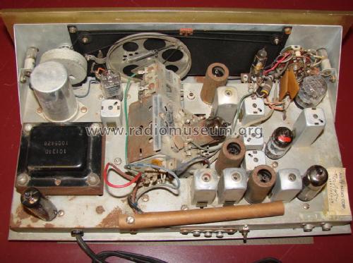
It was in good order when I received it, as far as I could see from outside. At first I bought a special transformer for separation and isolation purposes - you know perhaps, in Europe we use a mains voltage of 230 V. Then I took the chassis out of the wooden casing. And then - switch on - waiting - and then : no signal , but a terrible hum ! As expexted in accordance with your description ! First action : New main electrolytic capacitors, anymore, change of each electrolytic capacitor.
Result : FM-reception, but not in stereo in spite of the indication of the little neon bulb. My decision after all : to look and to measure each component beginning from the ratio-detector and stereo decoder.
I was very glad about the fact that I got the detailed manual from you ! Except for the inductances I renewed nearly each resistor and capacitor. And - suddenly I saw the main fault : wrong wiring of one notch filter ! Short circuit to ground (earth) of the right channel. This mistake was probably made by you and your father 40 years ago ! But I think you were not as familiar as I with electronic problems (I am an electrical engineer), and the manual says nearly nothing about mounting and wiring of the filters. After correction of the wiring and divers adjustments nearly everything was okay. Later on their occurred some minor difficulties, which I also was able to repair by and by.
Is it possible that another (third ?) person was helping you after assembling half the tuner ? There are some indications for my guess.
Today I hear FM-stereo everyday with the old tuner, and I am glad though it was very much work to reach the present good results.
I thought it could be interesting for you to have a look on it. So I attached some pictures, of the tuner (the casing is not yet ready for use) and of myself and of my parrot "Otto". She is always assisting and "helping".
Thank you and best regards from Germany
Rolf
at first sorry, my english is not so very good, but I will try to tell you the story. I am not sure if you remember : I purchased by an Ebay auction in September last year your old "Knight KG 50"-tube tuner which you had mounted together with your father in 1963.
It was in good order when I received it, as far as I could see from outside. At first I bought a special transformer for separation and isolation purposes - you know perhaps, in Europe we use a mains voltage of 230 V. Then I took the chassis out of the wooden casing. And then - switch on - waiting - and then : no signal , but a terrible hum ! As expexted in accordance with your description ! First action : New main electrolytic capacitors, anymore, change of each electrolytic capacitor.
Result : FM-reception, but not in stereo in spite of the indication of the little neon bulb. My decision after all : to look and to measure each component beginning from the ratio-detector and stereo decoder.
I was very glad about the fact that I got the detailed manual from you ! Except for the inductances I renewed nearly each resistor and capacitor. And - suddenly I saw the main fault : wrong wiring of one notch filter ! Short circuit to ground (earth) of the right channel. This mistake was probably made by you and your father 40 years ago ! But I think you were not as familiar as I with electronic problems (I am an electrical engineer), and the manual says nearly nothing about mounting and wiring of the filters. After correction of the wiring and divers adjustments nearly everything was okay. Later on their occurred some minor difficulties, which I also was able to repair by and by.
Is it possible that another (third ?) person was helping you after assembling half the tuner ? There are some indications for my guess.
Today I hear FM-stereo everyday with the old tuner, and I am glad though it was very much work to reach the present good results.
I thought it could be interesting for you to have a look on it. So I attached some pictures, of the tuner (the casing is not yet ready for use) and of myself and of my parrot "Otto". She is always assisting and "helping".
Thank you and best regards from Germany
Rolf
Rolf Nickel, 16.Apr.06