31-4A Ch= 31-4
Kriesler Radio Company; Newtown (Sydney)
- Paese
- Australia
- Produttore / Marca
- Kriesler Radio Company; Newtown (Sydney)
- Anno
- 1947–1951
- Categoria
- Radio (o sintonizzatore del dopoguerra WW2)
- Radiomuseum.org ID
- 185041
Kriesler 31-4
Clicca sulla miniatura dello schema per richiederlo come documento gratuito.
- Numero di tubi
- 5
- Principio generale
- Supereterodina (in generale); ZF/IF 455 kHz; 2 Stadi BF
- N. di circuiti accordati
- 8 Circuiti Mod. Amp. (AM)
- Gamme d'onda
- Onde medie (OM) e corte (OC).
- Tensioni di funzionamento
- Batteria di accumulatori, per tutto (es. autoradio, radio amatoriali) / 6 Volt
- Altoparlante
- AP magnetodinamico (magnete permanente e bobina mobile) / Ø 6 inch = 15.2 cm
- Materiali
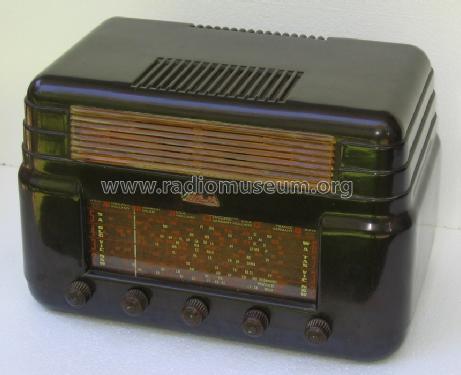
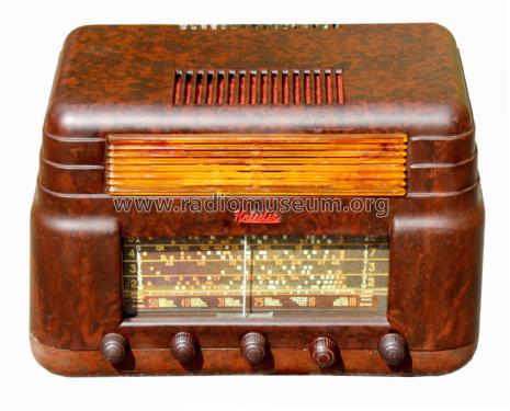
- Bachelite
- Radiomuseum.org
- Modello: 31-4A Ch= 31-4 - Kriesler Radio Company;
- Forma
- Soprammobile basso, con andamento orizzontale (grosse dimensioni).
- Dimensioni (LxAxP)
- 405 x 260 x 275 mm / 15.9 x 10.2 x 10.8 inch
- Annotazioni
-
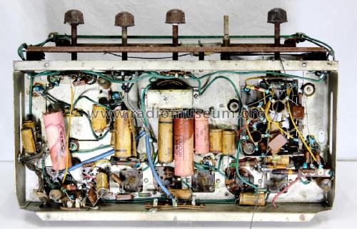
Kriesler advertised this set & other post-war models as a "Sealed Radio". Solder joints were marked to prevent unauthorised servicing & tampering.
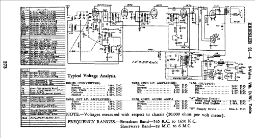
- CIRCUIT: As on 31-4 circuit.
- COIL KIT: Part No. 15-12 (AWA Tuning Condenser).
- DIAL GLASS: Part No. 50-28.
- SPEAKER: Part No. 70-22 (6" Permanent Magnet Type).
- OUTPUT TRANSFORMER: Part No. 18-37.
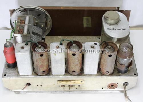
- VIBRATOR TRANSFORMER: Part No. 18-4.
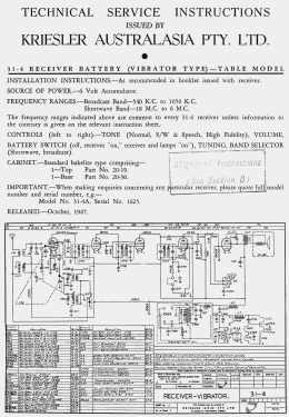
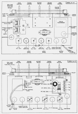
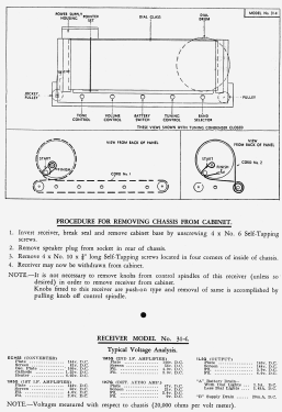
PROCEDURE FOR REMOVING CHASSIS FROM CABINET.
- Invert receiver, break seal and remove cabinet base by unscrewing 4 x No. 6 Self-Tapping screws.
- Remove speaker plug from socket in rear of chassis.
- Remove 4 x No. 10 x ⅜" long Self-Tapping screws located in four cporners of inside of chassis.
- Receiver may now be withdrawn from cabinet.
NOTE. - It is not necessary to remove knobs from control spindles of this receiver (unless so desired) in order to remove receiver from cabinet. Knobs fitted to this receiver are push-on type and removal of same is accomplished by pulling knob off control spindle.
This model uses the same cabinet design as the model 11-7 but has an extra knob. It uses a synchronous vibrator power unit.
- Prezzo nel primo anno
- 37.80 AUS £
- Riferimenti schemi
- Australian Official Radio Service Manual Vol. VI
- Letteratura / Schemi (1)
- - - Manufacturers Literature (Kriesler Technical Service Instructions.)
- Letteratura / Schemi (2)
- Australian Official Radio Service Manual AORSM (Volume 6, 1948, Page 273.)
- Letteratura / Schemi (3)
- Mingay's "Radio Diagram & I.F. Index
- Autore
- Modello inviato da Stuart Irwin. Utilizzare "Proponi modifica" per inviare ulteriori dati.
- Altri modelli
-
In questo link sono elencati 901 modelli, di cui 469 con immagini e 439 con schemi.
Elenco delle radio e altri apparecchi della Kriesler Radio Company; Newtown (Sydney)
Collezioni
Il modello fa parte delle collezioni dei seguenti membri.